Fracture Mechanics in Materials Science and Engineering
730 likes | 812 Views
Explore brittle and ductile fractures, crack propagation, and toughness in materials. Learn how cracks lead to material failure and the importance of preventing catastrophic outcomes. Discover theoretical fracture strength and fracture surfaces in real materials.

Fracture Mechanics in Materials Science and Engineering
E N D
Presentation Transcript
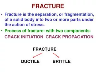
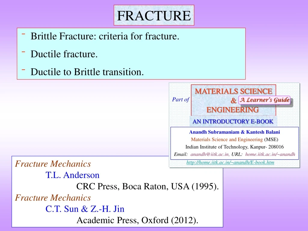
MATERIALS SCIENCE & ENGINEERING Part of A Learner’s Guide AN INTRODUCTORY E-BOOK Anandh Subramaniam & Kantesh Balani Materials Science and Engineering (MSE) Indian Institute of Technology, Kanpur- 208016 Email:anandh@iitk.ac.in, URL:home.iitk.ac.in/~anandh http://home.iitk.ac.in/~anandh/E-book.htm FRACTURE • Brittle Fracture: criteria for fracture. • Ductile fracture. • Ductile to Brittle transition. Fracture Mechanics T.L. Anderson CRC Press, Boca Raton, USA (1995). Fracture Mechanics C.T. Sun & Z.-H. Jin Academic Press, Oxford (2012).
Theoretical fracture strength and cracks • Let us consider a perfect crystalline material loaded in tension. Failure by fracture can occur if bonds are broken and fresh surfaces are created. • If two atomic planes are to be separated the force required initially increases to a maximum (Fmax) and then decreases. The maximum stress corresponding to Fmax is the theoretical strength t. This stress is given by: • E → Young’s modulus of the crystal • → Surface energy • a0 → Equilibrium distance between atomic centres By Energy consideration By atomistic approach For many metals ~ 0.01Ea0 • This implies the theoretical fracture strength is in the range of E/10 to E/6*. • The strength of real materials is of the order of E/100 to E/1000 (i.e. much lower in magnitude). Tiny cracks are responsible for this (other weak regions in the crystal could also be responsible for this). • *For Al:E=70.5 GPa, a0=2.86 Å, (111)= 0.704 N/m. • t = 13.16 GPa Fmax Cohesive force Applied Force (F) → 0 r → a0 • Cracks play the same role in fracture (of weakening)as dislocations play for plastic deformation.
Fracture • Fracture is related to propagation of cracks, leading to the failure of the material/component. • If there are no pre-existing cracks, then a crack needs to nucleate before propagation (to failure). Crack nucleation$ typically requires higher stress levels than crack propagation. • A crack is typically a ‘sharp*’ void in a material, which acts like a stress concentrator or amplifier. Hence, crack is a amplifier of a ‘far field’ mean stress. (Cracks themselves do not produce stresses!). [A crack is a stress amplifier !]. • Cracks in general may have several geometries. Even a circular hole can be considered as a very ‘blunt’ crack. A crack may lie fully enclosed by the material or may have ‘crack faces’ connected to the outer surface. Cracks connected with outer surface may be profoundly influenced by the environment. • Crack propagation leads to the creation of new surface area, which further leads to the increase in the surface energy of the solid. However, in fracture the surface energy involved (the fracture surface energy)is typically greater than the intrinsic surface energy as fracture involves ‘sub-surface’ atoms to some extent. Additionally, the fracture surface energy may involve terms arising out of energy dissipation due to micro-cracking, phase transformation and plastic deformation. A crack in a material Fracture surface energy (f) > Intrinsic surface energy () $ Regions of stress concentrations (arising from various sources) ‘help’ in the process. * More about this sooner 2a Click here What is meant by failure?
Fracture mechanics is the subject of study, wherein the a materials resistance to fracture is characterized. In other words the ‘tolerance’ of a material to crack propagation is analyzed*. • Crack propagation can be steady (i.e. slowly increasing crack length with time or load) or can be catastrophic (unsteady crack propagation, leading to sudden failure of the material)$. • ‘What dislocation is to slip, crack is to fracture’. • Under tensile loading if the stress exceeds the yield strength the material, the material begins to plastically deform. The area under the stress-strain curve is designated as the toughness in uniaxial tension. Toughness relates to the energy absorbed to fracture. • Similarly, in the presence of cracks we arrive at a material parameter, which characterizes the toughness of the material in the presence of cracks→ the fracture toughness. • In most materials, even if the material is macroscopically brittle (i.e. shows very little plastic deformation in a uniaxial tension test), there might be some ductility at the microscopic level. This implies that in most materials the crack tip is not ‘infinitely’ sharp, but is blunted a little (blunting occurs by plastic deformation). This further avoids the stress singularity at the crack tip as we shall see later. $ One of the important goals of material/component design is to avoid catastrophic failure. If crack propagation is steady, then we can practice preventive maintenance (i.e. replace the component after certain hours of service) → this cannot be done in the case of catastrophic failure. * Amongst its many other goals!
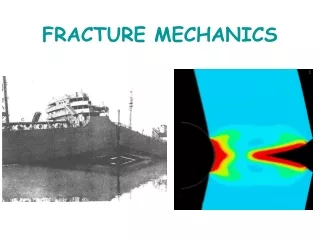
The subject of Fracture mechanics has its origins in the failure of WWII Liberty ships. In one of the cases the ship virtually broke into two with a loud sound, when it was in the harbour i.e. not in ‘fighting mode’. • This was caused by lack of fracture toughness at the weld joint, resulting in the propagation of ‘brittle cracks’ (i.e. crack propagation will little plastic deformation). The full list of factors contributing to this failure is in the figure below. • It is seen that welding was done for faster production, but this resulted in micro-cracks and residual stresses, which led to brittle crack propagation. The problem became ‘global’ as this provided continuity of crack path across plates (so instead of one plate breaking the entire ship ‘broke’). High sulphur in steel contributed to the brittleness of the plates. • Due to the cold sea waters the ships were harboured in, the hull material underwent a phenomenon known as ‘ductile to brittle transition (DBT)’ (about which we will learn more in this chapter). • Ironically, this ‘death’ of ships lead to the ‘birth’ of fracture mechanics as a systematic field of study. Continuity of the structure Welding instead of riveting BreakingofLiberty Ships Cold waters Residual stress High sulphur in steel Microcracks
Hard second phase in the material Funda Check What is a crack? • As we have seen crack is an amplifier of ‘far-field’ mean stress. The sharper the crack-tip, the higher will be the stresses at the crack-tip. It is a region where atoms are ‘debonded’ and an internal surface exists (this internal surface may be connected to the external surface). • Cracks can be sharp in brittle materials, while in ductile materials plastic deformation at the crack-tip blunts the crack (leading to a lowered stress at the crack tip and further alteration of nature of the stress distribution). • Even void or a through hole in the material can be considered a crack. Though often a crack is considered to be a discontinuity in the material with a ‘sharp’ feature (i.e. the stress amplification factor is large). • A second phase (usually hard brittle phase) in a lens/needle like geometry can lead to stress amplification and hence be considered a crack. Further, (in some cases) debonding at the interface between the second phase and matrix can lead to the formation of an interface cracks. • As the crack propagates fresh (internal) surface area is created. The fracture surface energy required for this comes from the strain energy stored in the material (which could further come from the work done by externally applied loads). In ductile materials energy is also expended for plastic deformation at the crack tip. • A crack reduces the stiffness of the structure (though this may often be ignored). Though often in figures the crack is shown to have a large lateral extent, it is usually assumed that the crack does not lead to an appreciable decrease in the load bearing area [i.e. crack is a local stress amplifier, rather than a ‘global’ weakener by decreasing the load bearing area].
Characteristics of Cracks Cracks can be characterized looking into the following aspects. • Its connection with the external free surface:(i) completely internal, (ii) internal cracks with connections to the outer surfaces, (iii) Surface cracks. Cracks with some contact with external surfaces are exposed to outer media and hence may be prone to oxidation and corrosion (cracking). We will learn about stress corrosion cracking later. • Crack length (the deleterious effect of a crack further depends on the type of crack (i, ii or iii as above). • Crack tip radius (the sharper the crack, the more deleterious it is). Crack tip radius is dependent of the type of loading and the ductility of the material. • Crack orientation with respect to geometry and loading. We will see modes of loading in this context soon. 2a ~ a
Modes of deformation of a cracked body (modes of fracture) How many ways are there to load a cracked body? • Three ideal cases of loading of a cracked body can be considered, which are called the modes of deformation: • Mode I: Opening mode • Mode II: Sliding mode • Mode III: Tearing mode • In the general case (for a crack in an arbitrarily shaped body, under an arbitrary loading), the mode is not pure (i.e. is mixed mode). The essential aspects of fracture can be understood by considering mode I. Mode I Modes of Deformation / fracture of a cracked body Mode II Mode III Important note: the loading specified and the geometry of the specimen illustrated for Mode II & III above do not give rise to pure Mode II and II deformation (other constraints or body shapes are required).
Fracture: Important Points • One of the goals of fracture mechanics is to derive a material property (the fracture toughness), which can characterize the mechanical behaviour of a material with flaws (cracks) in it. • Fracture can broadly be classified into Brittle and Ductile fracture. This is usually done using the macroscopic ductility observed and usually not taking into account the microscale plasticity, which could be significant. A ductile material is one, which yields before fracture. • Further, one would like to avoid brittle fracture, wherein crack propagation leading to failure occurs with very little absorption of energy (in brittle fracture the crack may grow unstably, without much predictability). • Three factors have a profound influence on the nature of fracture: (i) temperature, (ii) strain rate, (iii) the state of stress. • Materials which behave in a brittle fashion at low temperature may become ductile at high temperatures. When strain rate is increased (by a few orders of magnitude) a ductile material may start to behave in a brittle fashion. Temperature Factors affecting (the nature of) fracture Ductile material : y < f Strain rate State of stress Ductile Low Temperature Fracture Promoted by High Strain rate Brittle Triaxial state of State of stress
Funda Check Why do high strain rate, low temperature and triaxial state of stress promote brittle fracture? • High strain rate (by not giving sufficient time) and low temperature essentially have a similar effect of not allowing thermally activated motion of dislocations (i.e. ‘not helping’ plastic deformation by slip). • In specific cases some of the slip systems being active at high temperatures may become inactive at low temperatures. • By triaxial state of stress (SoS) we mean tensile stresses of same sign along ‘y’ and ‘z’ also. • Triaxial SoS does not promote crack propagation, but suppresses plastic deformation (click on link below to know more). Since plastic deformation is suppressed the crack tip remains sharp, thus promoting brittle fracture. • So for plastic deformation the following order is better: tri-axial < bi-axial < uni-axial. Click here to know more about which state of stress is good for plastic deformation Worst (to avoid brittle failure) best
Fractography • Considerable amount of information can be gathered regarding the origin and nature of fracture by studying the fracture surface. In fatigue failure for instance, we can know the place of origin of cracks, stable crack propagation regime, etc. • The fracture surface has to be maintained in pristine manner (i.e. oxidation, contact damage, etc. should be avoided) to get meaningful information from fractography. • It should be noted that a sample which shows very little macroscopic ductility, may display microscopic ductility (as can be seen in a fractograph). • Truly brittle samples show faceted cleavage planes, while ductile fracture surface displays a dimpled appearance. Fracture surface as seen in an SEM* * The Scanning Electron Microscope (SEM) with a large depth of field is an ideal tool to do fractography.
Classification of Fracture (based on various features) • Fracture can be classified based on: (i) Crystallographic mode, (ii) Appearance of Fracture surface, (iii) Strain to fracture, (iv) Crack Path, etc. (As in the table below). • Presence of chemical species at the crack tip can lead to reduced fracture stress and enhanced crack propagation. • Presence of brittle phase along the grain boundaries (Fe3C along GB in steel, glassy phase at GB in Si3N4 ceramics) can lead to inter-granular crack propagation. This preferred ‘weak’ path along grain boundaries implies low energy expenditure during fracture (i.e. low fracture toughness). Brittle cementite along grain boundaries along which crack can propagate
‘Early Days’ of the Study of Fracture • C.E. Inglis Stress based criterion for crack growth (local) → C.E. Inglis (seminal paper in 1913)[1] • Energy based criterion for crack growth (global)→ A.A. Griffith (seminal paper in 1920)[2](Work done on glass very brittle material). [1] C.E. Inglis, Stresses in a plate due to the presence of cracks and sharp corners, Trans. Inst. Naval Architechts 55 (1913) 219-230. [2] A.A. Griffith, The phenomena of rupture and flow in solids, Philos. Trans. R. Soc. Lond. A221 (1920) 163-198. → Fat paper!
Crack growth and failure Brittle Materials • Initially we try to understand crack propagation$ in brittle materials (wherein the cracks are sharp and there is very little crack-tip plasticity). The is the domain of Linear Elastic Fracture Mechanics (LEFM). • For crack to propagate the necessary global criterion (due to Griffith) and the sufficient local criterion (due to Inglis) have to be satisfied (as in figure below). • The kind of loading/stresses also matters. Tensile stresses* tend to open up cracks, while compressive stresses tend to close cracks. Global vs. Local It should be energetically favorable For crack growth to occur Sufficient stress concentration should exist at crack tip to break bonds Griffith Global Energy based Crack growth criteria Local Stress based Inglis $ Note: the crack propagation we will study in this chapter will be quasi-static (i.e. elastic wave propagation due to crack growth is ignored) * More on this later.
Stress based criterion for crack propagation (Inglis criterion) • In 1913 Inglis observed that the stress concentration around a hole (or a ‘notch’) depended on the radius of curvature of the notch. I.e. the far field stress (0) is amplified near the hole. [(max / 0) is the stress concentration factor ()]. • A ‘flattened’ (elliptical) hole (with a sharp tip) can be thought of as a crack. hole crack • 0→ applied “far field” stress • max → stress at hole/crack tip • → hole/crack tip radius • c → length of the hole/crack For sharp cracks Sharper the crack, higher the stress concentration. • Sharper the crack (smaller the ) more the stress amplification (higher value of max). A circular hole has a stress concentration factor of 3 [ = 3]. • From Inglis’s formula it is seen that the ratio of crack length to crack tip radius is important and not just the length of the crack. • One way of understanding this formula is that if max exceeds t (the theoretical fracture stress), then the material fails (by the extension of the crack). • This is in spite of the fact that the applied stress is of much lower magnitude than the theoretical fracture stress. For a circular hole = c
For a crack to propagate the crack-tip stresses have to do work to break the bonds at the crack-tip. This implies that the ‘cohesive energy’ has to be overcome. • If there is no plastic deformation or any other mechanism of dissipation of energy, the work done (energy) appears as the surface energy (of the crack faces). • The fracture stress (f) (which is the ‘far field’ applied stress) can be computed using this approach. Note that the fracture stress is of the order of E (i.e. in GPa). • f→ fracture stress (applied “far-field”) • → crack tip radius • c → length of the crack • a0→ Interatomic spacing
Griffith’s criterion for brittle crack propagation • We have noted that the crack length does not appear ‘independently’ (of the crack tip radius) in Inglis’s formula. Intuitively we can feel that longer crack must be more deleterious. • Another point noteworthy in Inglis’s approach is the implicit assumption that sufficient energy is available in the elastic body to do work to propagate the crack. (‘What if there is insufficient energy?’) (‘What if there is no crack in the body?’). Also, intuitively we can understand that the energy (which is the elastic energy stored in the body) should be available in the proximity of the crack tip (i.e. energy available far away from the crack tip is of no use!). • Keeping some of these factors in view, Griffith proposed conditions for crack propagation:(i) bonds at the crack tip must be stressed to the point of failure (as in Inglis’s criterion),(ii)the amount of strain energy released (by the ‘slight’ unloading of the body due to crack extension) must be greater than or equal to the surface energy of the crack faces created. • The second condition can be written as: • Us→ strain energy • U→ surface energy (Energy per unit area: [J/m2]) • dc → (‘infinitesimal’) increase in the length of the crack (‘c’ is the crack length) Essentially this is like energy balance (with the ‘=‘ sign) → the surface energy for the extended crack faces comes from the elastically stored energy (in the fixed displacement case) We look at the formulae for Us and U next.
The strain energy released on the introduction of a very narrow elliptical double ended crack of length ‘2c’ in a infinite plate of unit width (depth), under an uniform stress a is given by the formula as below. • This is because the body with the crack has a lower elastic energy stored in it as compared to the body without the crack (additionally, the body with the crack is less stiffer). Also, the assumption is that the introduction of a crack does not alter the far-field stresses (or the load bearing area significantly). • Notes: The units of Us is [J/m] (Joules per meter depth of the crack→ as this is a through crack). Though Us has a symbol of energy, it is actually a difference between two energies (i.e. two states of a body→ one with a crack and one without). Half crack length ‘c’ appears in the formula. E is assumed constant in the process(the apparent modulus will decrease slightly). a is the ‘far field’ stress (this may result from displacements rather than from applied forces see note later). Should be written with a ve sign if U = (Ufinal Uinitial) For now we assume that these stresses arise out of ‘applied’ displacements
The formula for Uscan be appreciated by considering the energy released from a circular region of diameter 2c as in the figure below. (The region is cylindrical in 3D). • The energy released is: (1) • The computation of the actual energy released is more involved and is given by the formula as noted before: Energy released from this circular region is given by the formula (1) as above (not a true value, but to get a feel of the predominant region involved). Plane stress condition Hence • For a body in plane strain condition (i.e. ~ thick in the z-direction, into the plane of the page), E is replaced with E/(12): As plane strain is more severe on the material it is better to do experiments in plane strain condition. Plane strain condition
The surface energy of the crack of length 2c & unit width/depth is: • This is the difference in the energy between a body with a crack and one without a crack. • As pointed out before, the surface energy is the fracture surface energy and not just the surface free energy. The origin of this energy is contributions from dissipative mechanisms like plastic deformation, micro-cracking & phase transformation, in addition to the energy of the ‘broken bonds’. • The units are Joules per meter depth of the body: [J/m]. Important note • The “Griffith experiment” is easily understood in displacement control mode (i.e. apply a constant displacement and ‘see’ what happens to the crack) and is more difficult to comprehend it in the force control mode (by applying constant ‘far-field’ forces). • In force control mode, the forces do work on the system and hence the ‘energy accounting’ process is more involved. • Hence, it is better to visualize as arising from ‘far field’ applied displacements.
Now we have the formulae for Us & U(which are required to write down the Griffith’s condition): • LHS increases linearly with c, while RHS is constant. • The ‘equal to’ (=) represents the bare minimum requirement (i.e. the critical condition) → the minimum crack size, which will propagate with a ‘balance’ in energy (i.e. between elastic energy released due to crack extension and the penalty in terms of the fracture surface energy). • The critical crack size (c*): (Note that ‘c’ is half the crack length internal) • A crack below this critical size will not propagate under a constant stress a. • Weather a crack of size greater than or equal to c* will propagate will depend on the Inglis condition being satisfied at the crack-tip (i.e. sufficient stress concentration should exist). • This stress a now becomes the fracture stress (f)→ cracks of length c* will grow (unstably) if the stress exceeds f (= a).
Understanding Griffith’s equation • According to Griffith’s criterion: At criticality (written with ‘*’) crack propagation just starts: Putting the ‘*’ around the variables: Since, * is f : Which, can be written in two ways: • This can be understood as follows: keep displacement imposed on the ends of the specimen constant (& hence far field) and keep increasing ‘c’ till the crack beings to propagate (& hence far field = f). • Else, one can keep ‘c’ constant and increase displacements (leading to an increase in far field) till crack propagation starts (i.e. c c*, f). At constant c (= c*)when exceeds f then specimen fails Griffith Plane strain conditions
An alternate way of understanding the Griffith’s criterion (energy based), though personally I prefer the previous method (discussed in the last few slides). 0 • This change in energy (U) should be negative with an increase in crack length (or at worst equal to zero). I.e. (dU/dc) ≤ 0. • At c* the slope of U vs c curve is zero [(dU/dc)c*= 0]. This is a point of unstable equilibrium. • With increasing stress the value of c* decreases (as expected→ more elastic strain energy stored in the material). 0 Positive slope Increasing stress U → U → c → Stable cracks Negative slope Unstable cracks c → Equations for ready reference
Griffith versus Inglis criteria • For very sharp cracks, the available elastic energy near the crack-tip, will determine if the crack will grow. • On the other hand if available energy is sufficient, then the ‘sharpness’ of the crack-tip will determine if the crack will grow. A sharp crack is limited by availability of energy, while a blunt crack is limited by stress concentration. Griffith Inglis
‘Modern’ Fracture Mechanics • Stress Intensity Factor (K)Material Parameter Fracture Toughness (KC) • Energy Release Rate (G) Material Parameter Critical Energy Release Rate (GC) • J-integral (J)Material Parameter: JC • Crack Tip Opening Displacement (CTOD) ()Material Parameter: C [1] G.R. Irwin, “Fracture Dynamics”, in: “Fracture of Metals”, ASM, Cleaveland, OH, 1948, pp.147-166. [2] G.R. Irwin, “Analysis of stresses and strains near the end of a crack traversing a plate, J. Appl. Mech 24 (1957) 361-364.
Fracture Mechanics • Historically (in the ‘old times’ ~1910-20) fracture was studied using the Inglis and Griffith criteria, wherein fracture stress (f) was calculated either using a global or local criterion. • The birth of fracture mechanics (~1950+) led to the concepts of stress intensity factor (K) and energy release rate (G) (due to Irwin and others). These concepts worked well in the domain of ‘linear elasticity’ (LEFM); i.e. for brittle materials. Crack tip stresses were characterized by the stress intensity factor. • In the presence of crack tip plasticity some of these concepts were extended if the crack tip plasticity was small (small scale yielding). • In ductile materials with large plastic deformation at the crack tip, concept of J-integral was evolved, wherein stress fields ahead of the crack tip are termed as ‘HRR’ fields and the J-integral characterizes the field intensity of the crack tip. • The concept of Crack Tip Opening Displacement (CTOD) was also proposed to characterize cracks in ductile materials.
Concept of Energy Release Rate (G) • G is defined as the total potential energy () decrease during unit crack extension (dc). ‘G’ is also referred to as the crack extension force and is given by: The potential energy is a difficult quantity to visualize. In the absence of external tractions (i.e. only displacement boundary conditions are imposed), the potential energy is equal to the strain energy stored: = Us.* With displacement boundary conditions only. ‘G’ has units of [J/m2] = [N/m] As we have seen, Us is given by: • Crack growth occurs if G exceeds (or at least equal to) a critical value GC, which is the fracture toughness of the material. For perfectly brittle solids: GC = 2f (i.e. this is equivalent to Griffith’s criterion). * It is better to understand the basics of fracture with fixed displacement boundary conditions (without any surface tractions).
Relation between K and G • In spite of the fact that ‘G’ has a more direct physical interpretation for the crack growth process, usually we work with ‘K’ as it is more amenable to theoretical computation. • ‘K’ can be related to ‘G’ using the following equations:
Stress fields at crack tips • For a body subjected far field biaxial stress 0, with a double ended crack of length 2c, the stress state is given by (this is mode-I loading): (1) (2) Fig.1 (3) • Note the inverse square root (of r) singularity at the crack tip. The intensity of the singularity is captured byKI(the Stress Intensity Factor). I.e. KI is the scaling factor for the singularity. • As no material can withstand infinite stresses (in ductile materials plasticity will intervene), clearly the solutions are not valid exactly at (& ‘very near’) the crack tip. • At = 0 and r → the stresses (xx & yy) should tend to 0. This is not the case, as seen from the equations ((1) & (2)). This implies that the equations should be used only close to crack tip (with little errors) or additional terms must be added to the equations.
Understanding the stress field equation (1) → Half the crack length (for a fully internal crack) Indicates mode I ‘loading’ ‘Shape factor’ related to ‘Geometry’ • “KI(the Stress Intensity Factor) quantifies the magnitude of the effect of stress singularity at the crack tip”[1]. K has units of [N/m2.m] or [Pam] or typically [MPam]. • Quadrupling the crack length is equivalent to doubling the stress ‘applied’. Hence, K captures the combined effect of crack length and loading. The remaining part in equation(1) is purely the location of a point in (r, ) coordinates (where the stress has to be computed). • Note that there is no crack tip radius () in the equation! The assumptions used in the derivation of equations (1-3) are: = 0, infinite body, biaxial loading. • The factor ‘Y’ is considered in the next page. [1] Anthony C. Fischer-Cripps, “Introduction to Contact Mechanics”, Springer, 2007.
The Shape factor (Y) • It is obvious that the geometry of the crack and its relation to the body will play an important role on its effect on fracture. • The factor Y depends on the geometry of the specimen with the crack. • Y=1 for the body considered in Fig.1 (double ended crack in a infinite body). • Y=1.12 for a surface crack. The value of Y is larger (by 12%) for a surface crack as additional strain energy is released (in the region marked dark grey shade in the figure below), due to the presence of the free surface. • Y=2/ for a embedded penny shaped crack. • Y=0.713 for a surface half-penny crack.
Region of K-Dominance • The crack tip fields consists of two parts: (i) singular part (which blow up near the crack tip) and (ii) the non-singular part. • The region near the crack tip, where the singular part can describe the stress fields is the K-Dominance region. This is the region where the stress intensity factor can be used to characterize the crack tip stress fields. • In materials where the crack tip plastic zone is smaller than the K-dominance region (also called the Small Scale Yielding (SSY) regime, concepts of linear elastic fracture mechanics (LEFM) can be used with little error.
Fracture Toughness (Irwins’s K- Based) • One of the important goals of fracture mechanics is to derive a material parameter, which characterizes cracks in a material. This will be akin to yield stress (y) in a uniaxial tension test (i.e. y is the critical value of stress, which if exceeded ( y) then yielding occurs). • The criterion (critical condition) for fracture in mode-I can be written as: Where, KICis the critical value of stress intensity factor (K) and is known as Fracture Toughness • KIC is a material property (like yield stress) and can be determined for different materials using standard testing methods. KIC is a microstructure sensitive property. • The focus here is the ‘local’ crack tip region and not ‘global’, as in the case of Griffith’s approach. • All the restrictions/assumptions on K will apply to KIC: (i) material has a liner elastic behaviour (i.e. no plastic deformation or other non-linear behaviour), (ii) inverse square root singularity exists at crack tip (eq. (1)), (iii) the K-dominance region characterizes the crack tip. (1)
Fracture Toughness* (KIC) for some typical materials [1] * We have already noted that fracture toughness is a microstructure sensitive property and hence to get ‘true’ value the microstructure has to be specified. ** Note the strange units for fracture toughness! [1] Fracture Mechanics, C.T. Sun & Z.-H. Jin, Academic Press, Oxford (2012).
Funda Check Is KIC really a material property like y? • Ideally, we would like KIC (in mode-I loading) (KIIC & KIIIC will be the corresponding material properties under other modes of loading$) to be a material property, independent of the geometry of the specimen*. In reality, KIC depends on the specimen geometry and loading conditions. • The value KIC is especially sensitive to the thickness of the specimen. A thick specimen represents a state that is closer to plane strain condition, which tends to suppress plastic deformation and hence promotes crack growth (i.e. the experimentally determined value of KIC will be lower for a body in plane strain condition). On the other hand, if the specimen is thin (small value ‘t’ in the figure), plastic deformation can take place and hence the measured KIC will be higher (in this case if the extent of plastic deformation is large then KI will no longer be a parameter which characterizes the crack tip accurately). • To use KIC as a design parameter, we have to use its ‘conservative value’. Hence, a minimum thickness is prescribed in the standard sample for the determination of fracture toughness. • This implies that KIC is the value determined from ‘plane strain tests’. $ Without reference to mode we can call it KC. * E.g. Young’s modulus is a material property independent of the geometry of the specimen, while stiffness is the equivalent ‘specimen geometry dependent’ property..
Q & A I seem totally messed up with respect to the proliferation of fracture criteria! How do I understand all this? • First one has to decide if the material is brittle or ductile (i.e. if the crack tip is sharp or blunted). • If the material is brittle one has to decide if the material is linear elastic or not. • For linear elastic materials we can apply the concept of K and use material property KC (usually in mode-I these quantities become KI and KIC). We could also use G & GC. • If the material is ductile then we need to determine if the plastic zone is small compared to the K dominance zone. If yes then we can continue to use the concepts of K and G. • If crack tip plasticity is large, then we have to use concepts like J-integral and CTOD. The crack tip stress fields in this case is given by the HRR fields. (Noting that technically JC is for crack nucleation). • Essentially there are two approaches: global (energy based) and local (stress based). • For linear elastic materials the energy and stress field approaches can be considered equivalent.
Ductile fracture • In ductile materials: Crack-tip stresses lead to plastic deformation at the crack-tip, which further leads to crack tip blunting. Energy is consumed due to plastic deformation at the crack-tip (which comes from elastic strain energy). This implies less energy is available for crack growth (& creation of new surfaces). Crack-tip blunting leads to a reduced stress amplification at the crack-tip. Blunting will avoid ‘stress singularity’ at the crack tip and may lead to a maximum stress at a certain distance from the crack-tip (as in the figure below). Crack-tip blunting will lead to an increased resistance to crack propagation (i.e. increased fracture toughness). * Note: For a material to be classified as ductile it need not display large strain in a tensile test.
Crack propagation in ductile materials • In brittle materials the maximum crack opening stress (mode-I) is at the crack tip and hence crack propagation involves breaking of bonds at the crack tip. • In ductile materials the maximum of stress lies a little ahead of the crack tip. • In this scenario the mechanism of cracking changes. • Void(s) nucleate in the region of highest stress (usually at some heterogeneity). • The region between the void and the crack tip acts like a tensile specimen andmicrovoids form in this region. Crack extension occurs by the coalescence of these micro-voids.
Funda Check What happens to a ‘crack’ in a ductile material? • High magnitude of crack tip stresses can cause yielding at the crack tip (plastic deformation). • This leads to crack tip blunting, which reduces the stress amplification. • There develops a zone ahead of the crack tip known as the process zone. Funda Check What else can happen at the crack tip due to high stresses? • High magnitude of crack tip stresses can cause: phase transformation (tetragonal to monoclinic phase in Yttria stabilized Zirconia), Complete slide
Fracture Toughness in Ductile Materials • We have seen that the crack tip gets blunted in ductile materials. As the stress intensity factor approach assumes that the material in linear elastic, the solutions obtained are not applicable to ductile materials. • However, if the plastic deformation zone around the crack tip is smaller than the K-dominance zone, then the LEFM approach can be used for ductile materials also (with minimum errors). This is referred to as Small Scale Yielding (SSY). • Irwin[1] estimated the size of the plastic deformation zone (near the crack tip):(Assuming the plastic deformation to be small). • If the yielding is large, then the applicability of LEFM breaks down. As a first approach Irwin[1] suggested the use of ‘effective crack length’ instead of crack length, to obtain an ‘effective stress intensity factor’. Effective crack length = crack length + ½(plastic zone size). • Further Dugdale[2] presented a strip yielding zone model to determine the plastic zone size (in thin cracked sheets). [1] G.R. Irwin, Proc. 7th Sagamore Ordnance Materials Conference, Syracuse Univ., 1960, p. IV-63. [2] D.S. Dugdale, J. Mech. Phys. Solids 8 (1960) 100.
The concept of Crack Opening Displacement (COD) was proposed by Wells[1]. This model can be used both in case of moderate and large yielding. • The energy release rate (G) concept was generalized by Rice[2] to include non-linear elastic and elastic-plastic materials. He represented the energy release rate by a path dependent line integral, the J-integral. • Using concepts from deformation plasticity Rice and Rosengren[3] along with Hutchinson[4] derived the crack tip stress fields in the presence of plastic deformation (called the HRR fields). They showed that the J-integral characterizes the crack tip with plastic deformation analogous to the stress intensity factor (K) in LEFM. Technically, the J-integral should be used for crack initiation only. [1] A.A. Wells, Proc. Crack Propagation Symp., Vol. 1, Paper 84, Cranfield, UK, 1961. [2] J.R. Rice, ASME J. Appl. Mech. 35 (1968) 379. [3] J.R. Rice, G.F. Rosengren, J. Mech. Phys. Sol. 16 (1968) 1. [4] J.W. Hutchinson, J. Mech. Phys. Sol. 16 (1968) 13.
Orowan’s modification to the Griffith’s equation to include “plastic energy”
Summary of Fracture Criteria • The table below summarizes many criteria found in standard literature. Some details can be found in other pages of the chapter.
Ductile – brittle transition • Certain materials which are ductile at a given temperature (say room temperature), become brittle at lower temperatures. The temperature at which this happens is terms as the Ductile Brittle Transition Temperature (DBTT). • As obvious, DBT can cause problems in components, which operate in ambient and low temperature conditions. • Typically the phenomena is reported in polycrystalline materials. Deformation should be continuous across grain boundary in polycrystals for them to be ductile. This implies that five independent slip systems should be operative (this is absent in HCP and ionic materials). • This phenomenon (ductile to brittle transition) is not observed in FCC metals (they remain ductile to low temperatures). • Common BCC metals become brittle at low temperatures (as noted before a decrease in temperature can be visualized as an increase in strain rate, in terms of the effect on the mechanical behaviour). • As we have noted before a ductile material is one which yields before fracture (i.e. its yield strength is lower in magnitude than its fracture strength).
What causes the ductile to brittle transition phenomenon? • Both the fracture stress (f) and the yield stress (y) are temperature dependent. However, as slip is a thermally activated process, the yield stress is a stronger function of temperature as compared to the fracture stress. • If one looks at the Griffith’s criterion of fracture, f has a slight dependence on temperature as E increases with decreasing the temperature ( also has a slight temperature dependence, which is ignored here). y on the other hand has a steeper increase with decreasing temperature. y DBTT • Ductile y < f yields before fracture • Brittle y > f fractures before yielding f f , y→ Ductile Brittle Griffith’s criterion T→
f f , y→ y(BCC) y(FCC) T→ DBTT No DBTT