FRACTURE
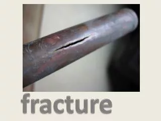
FRACTURE. Fracture is the separation, or fragmentation, of a solid body into two or more parts under the action of stress. Process of fracture- with two components- CRACK INITIATION CRACK PROPAGATION FRACTURE DUCTILE BRITTLE.

FRACTURE
E N D
Presentation Transcript
FRACTURE • Fracture is the separation, or fragmentation, of a solid body into two or more parts under the action of stress. • Process of fracture- with two components- CRACK INITIATIONCRACK PROPAGATION FRACTURE DUCTILE BRITTLE
Fracture Behavior of Bulk Crystalline Materials • Fundamentals of Fracture • Ductile Fracture • Brittle Fracture • Crack Initiation and Propagation • Fracture Mechanics • Fracture Toughness • Design
Fundamentals of Fracture • A separation of an object into two or more pieces in response to active stresses far below the melting temperature of the material. • Atoms on the surface of a material give rise to a surface energy • Stems from the open bonds on the outer atoms • Grain boundaries also contain a surface energy due to the large number of open bonds • Two steps in the process of fracture: • Crack initiation • Propagation
Fundamentals of Fracture • Simple fracture may occur by one of two methods, ductile or brittle • Dependent upon the plastic deformation of the material • Properties which influence the plastic deformation of a material • Modulus of elasticity • Crystal structure
Fundamentals of Fracture • (a) Highly ductile fracture • (b) Moderately ductile fracture with necking Called a cup-and -cone fracture • Most common form of ductile fracture • (c) Brittle fracture No plastic deformation occurring
Fundamentals of Fracture • (a) Highly ductile fracture • (b) Moderately ductile fracture with necking Called a cup-and -cone fracture • Most common form of ductile fracture • (c) Brittle fracture No plastic deformation occurring
Ductile Fracture • Involves a substantial amount of plastic deformation and energy absorption before failure. • Crack propagation occurs very slowly as the length the crack grows. • Often termed a stable crack, in that it will not grow further unless additional stress is applied • The fracture process usually consists of several stages
Ductile Fracture • (a) Initial necking • (b) Cavity formation • (c) Cavities form a crack • (d) Crack propagation • (e) Final shear occurs at an angle of 45°, where shear stress is at a maximum
Brittle Fracture • Exhibits little or no plastic deformation and low energy absorption before failure. • Crack propagation spontaneous and rapid • Occurs perpendicular to the direction of the applied stress, forming an almost flat fracture surface • Deemed unstable as it will continue to grow without the aid of additional stresses • Crack propagation across grain boundaries is known as transgranular, while propagation along grain boundaries is termed intergranular
Ductile fracture A pure and inclusion free metal can elongate under tension to give approx. 100% RA and a point fracture. The central fracture surface consists of numerous cup-like depressions generally called dimples. Dimple size depends largely on the number of inclusion sites.
Cleavage patterns in HS steel fracture (x12000) Dimples in a ductile fracture of mild steel (x5000) Intergranular fracture in low alloy steel (x1500) Fatigue striations in Nimonic 80A (x7000)(A.Strang)
Cohesive stress-strain curves, B, N, and F. If the two curves intersect at Y, brittle fracture occurs preceded by plastic deformation, which decreases as the cohesive strength curve becomes lower with respect to the yield stress-strain curve. Orowan has shown that if the yield stress is denoted by Y, the strength for brittle fracture by B (both Y and B depend on the plastic strain), and the initial value of Y (for strain = 0) by Y0 The following are the relationships: • The material is brittle if B < Y0; • The material is ductile but notch-brittle if Y0 < B < 3Y0 • The material is not notch-brittle if 3Y < B.
Brittle fracture • Brittle fracture is characterised by the very small amount of work absorbed and by a crystalline appearance of the surfaces of fracture, often with a chevron pattern pointing to the origin of fracture, due to the formation of discontinuous cleavage cracks which join up
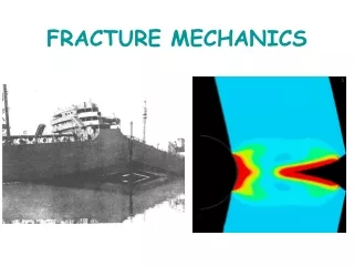
It can occur at a low stress of 75-120 MPa with great suddenness; the velocity of crack propagation is probably not far from that of sound in the material in this type of fracture plastic deformation is very small, and the crack need not open up considerably in order to propagate, as is necessary with a ductile failure.
The work required to propagate a crack is given by Griffith`s formula: σ = tensile stress required to propagate a crack of length cγ = surface energy of fracture facesE = Young`s modulus Orowan modified the Griffith theory to include a plastic strain energy factor, p
Location of local stresses near a crack tip in cylindrical coordinates
Most alloys contain second phases which lose cohesion with the matrix or fracture and the voids so formed grow as dislocations flow into them. • Coalescence of the voids forms a continuous fracture surface followed by failure of the remaining annulus of material usually on plane at 45° to the tension axis. • The central fracture surface consists of numerous cup-like depressions generally called dimples. • The shape of the dimples is strongly influenced by the direction of major stresses-circular in pure tension and parabolic under shear
TYPICAL FATIGUE STRESS CYCLES (a) REVERSED (b) REPEATED (c ) IRREGULAR OR RANDOM
Atomistic Simulation of Brittle Fracture • Image of simulated brittle fracture • Mode I fracture
Crack Initiation and Propagation • Cracks usually initiate at some point of stress concentration • Common areas include scratches, fillets, threads, and dents Propagation occurs in two stages: • Stage I: propagates very slowly along crystallographic planes of high shear stress and may constitute either a large or small fraction of the fatigue life of a specimen • Stage II: the crack growth rate increases and changes direction, moving perpendicular to the applied stress
Crack Initiation and Propagation • Double-ended crack simulations
Fracture Mechanics • Uses fracture analysis to determine the critical stress at which a crack will propagate and eventually fail • The stress at which fracture occurs in a material is termed fracture strength • For a brittle elastic solid this strength is estimated to be around E/10, E being the modulus of elasticity • This strength is a function of the cohesive forces between the atoms • Experimental values lie between 10 and 1000 times below this value • These values are a due to very small flaws occurring throughout the material referred to as stress raisers
Fracture Mechanics • If we assume that the crack is elliptical in shape and it’s longer axis perpendicular to the applied stress, the maximum stress at the crack tip is: • Fracture will occur when the stress level exceeds this maximum value .
Fracture Mechanics • The ratio σm/ σ0 is known as the stress concentration factor, Kt : • It is the degree to which an external stress is amplified at the tip of a small crack
Griffith Theory of Brittle Fracture • The critical stress required for crack propagation in a brittle material is given by: • E = modulus of elasticity • gs= specific surface energy • a = half the length of an internal crack • Applies only in cases where there is no plastic deformation present.
Fracture Toughness • Stresses near the crack tip of a material can also be characterized by the stress intensity factor, K, • A critical value of K exists, similar to the value sc, known as fracture toughness given by: • Y is a dimensionless parameter that depends on both the specimen and crack geometries. • Carries the unusual units of
FRACTURE TOUGHNESS Yielding near crack tip.
Plane Strain Fracture Toughness • Kc depends on the thickness of plate in question up to a certain point when it becomes constant • This constant value is known as the plane strain fracture toughness denoted by: • The I subscript corresponds to a mode I crack displacement • KIc values are used most often because they represent the worst case scenario • Brittle materials have low KIc values, giving to catastrophic failure • ductile materials usually have much larger KIc values • KIc depends on temperature, strain rate, and microstructure • Increases as grain size decreases
Fracture Toughness in Design • There are three crucial factors which must be considered in designing for fracture: • The fracture toughness (Kc or plane strain KIc) • the imposed stress (s) • and the flaw size (a) • It must be determined first what the limits and constraints on the variables will be • Once two of them are determined, the third will be fixed • For example, if the stress level and plane strain fracture toughness are fixed, then the maximum allowable flaw size must be:
Ductile Fracture • Involves a substantial amount of plastic deformation and energy absorption before failure. • Crack propagation occurs very slowly as the length the crack grows. • Often termed a stable crack, in that it will not grow further unless additional stress is applied • The fracture process usually consists of several stages
Fracture Mechanics • If we assume that the crack is elliptical in shape and it’s longer axis perpendicular to the applied stress, the maximum stress at the crack tip is: • Fracture will occur when the stress level exceeds this maximum value .