Download
1 / 24
260 likes | 562 Views
Quadrature-Field Theory and Induction-Motor Action. Single-phase induction motor cannot develop a rotating magnetic field Needs an “auxiliary” method That method is another (auxiliary) winding. Single-Phase Squirrel-Cage Induction Motor. There are two “Main Poles”. Squirrel-Cage Rotor.

E N D
Quadrature-Field Theoryand Induction-Motor Action • Single-phase induction motor cannot develop a rotating magnetic field • Needs an “auxiliary” method • That method is another (auxiliary) winding ECE 441
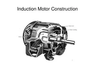
Single-Phase Squirrel-Cage Induction Motor There are two “Main Poles” Squirrel-Cage Rotor Single-Phase Mains Supply ECE 441
Excite the Main Winding Stator flux is produced across the air gap – as shown, it is increasing in the downward direction. The squirrel-cage rotor responds with a mmf in the opposite (upward) direction. Magnetic axis of the rotor is in line with the magnetic axis of the stator – no rotation! ECE 441
Current “out of” the page “Main” pole flux (Φ) increasing in the downward direction Rotor mmf develops in the upward direction Current “into” the page ECE 441
Cause the rotor to turn clockwise Rotor conductors cut through the main pole flux. Current is induced in the rotor bars as shown, producing a magnetic flux perpendicular to the main pole flux. This is known as “Quadrature” flux. ECE 441
The quadrature flux is sustained as the rotor conductors shift their positions – other conductors replace them. ECE 441
Phase Relationship Between the Direct and Quadrature Flux The “speed” voltage is in phase with the flux that created it, and the flux due to current is in phase with the current that caused it. The instantaneous amplitudes of the direct and quadrature flux are shown above. ECE 441
Resultant Flux • Determine from ECE 441
Resultant Flux Rotates CW ECE 441
Provides “direct” flux Start winding Provides quadrature flux Ensures phase difference between winding currents ECE 441
Equivalent Circuit ECE 441
Purpose of the “Phase-Splitter” • Make the current in the Auxiliary Winding out of phase with the current in the Main Winding. • This results in the quadrature field and the main field being out of phase. • The locked-rotor torque will be given by ECE 441
Example 6-1 • The main and auxiliary windings of a hypothetical 120 V, 60 Hz, split-phase motor have the following locked-rotor parameters: • Rmw=2.00 Ω Xmw=3.50 Ω • Raw=9.15 Ω Xaw=8.40 Ω • The motor is connected to a 120 V system. Determine ECE 441
Example 6-1 continued • The locked-rotor current in each winding ECE 441
Example 6-1 continued ECE 441
Example 6-1 continued • The phase displacement angle between the main and auxiliary currents ECE 441
Example 6-1 continued • The locked-rotor torque in terms of the machine constant ECE 441
Example 6-1 continued • External resistance required in series with the auxiliary winding in order to obtain a 30 phase displacement between the currents in the two windings. ECE 441
Example 6-1 continued • Phasor diagram for the new conditions ECE 441
Example 6-1 continued ECE 441
Example 6-1 continued ECE 441
Example 6-1 continued • Locked-rotor torque for the condition in d ECE 441
Example 6-1 continued • % increase in locked-rotor torque due to the adding of additional resistance ECE 441