Download
1 / 52
530 likes | 743 Views
Introduction to x DSL Part I. Yaakov J. Stein Chief Scientist RAD Data Communications. Introduction to xDSL. I Background history, theoretical limitations II Modems line codes, duplexing, equalization, error correcting codes, trellis codes III xDSL - What is x?

E N D
IntroductiontoxDSL Part I Yaakov J. Stein Chief ScientistRAD Data Communications
Introduction to xDSL I Background history, theoretical limitations II Modems line codes, duplexing, equalization, error correcting codes, trellis codes III xDSL - What is x? x=I,A,S,V - specific technologies competitive technologies
What is DSL? Drinking Straw Line A sophisticated method that enables used drinking straws to be employed as fire hoses under certain circumstances Can this work? • If you know enough about drinking straws • If you don’t apply to much pressure • If you use a lot of tricks Why not buy a new fire hose?
Timeline of UTP 1800-1876 Early 1800s first telegraph experiments 1832-3 Henry, Gauss, Weber set up communications systems 1836 Salva and Steinheil demostrate that a single wire suffices 1837 Samuel Morse receives US patent for telegraph Wheatstone demostrates 5 needle telegraph in London 1843 Morse sends “What hath God wrought?” to Alfred Vail 1844 First commercial telegraph line - 2 wires on cross-piece 1850s Morse’s patent expires Western Union connects US with single steel wires 1858 First subatlantic telegraph cable connects US with Europe
Timeline of UTP 1876-1877 Feb 14 1876 Alexander Graham Bell’s 29’th birthday Bell files for patent on telephone Elisha Gray files for caveat two hour later Mar 7 1876 Patent 174,465 issued to Bell Mar 10 1876 Bell spills acid on his pants “Mr. Watson come here, I want you” 1877 Long distance telephone experiments (using telegraph wires) 1878 Telephone exchange in New Haven Conn Theodore Vail becomes general manager of Bell Telephone
Timeline of UTP 1877-1899 1879 Four 7-conductor cables laid over Brooklyn bridge Technician reports on cross-talk Bell Telephone establishes patent division 1881 Bell receives patent for “metallic circuit” 1888 Western Electric establishes standard cable 1891 Paper pulp insulation standard cable
Timeline of UTP 1900-1918 1900 Michael Pupin invents loading coil 1912 New standard cable 1915 First use of amplifiers First use of repeaters Transcontinental long distance line (#6 gauge) 1918 Carrier system (5 calls) Baltimore-Pittsburgh
The importance of Theodore Vail Theodore Who? Son of Alfred Vail (Morse’s coworker) Ex-head of US post office First general manager of Bell Telephone Company Why is he so important? Made telephone service into a business Organized PSTN and COs (Bell sold telephones!) Established principle of reinvestment in R&D Established Bell Telephones IPR division Executed merger with Western Union to form AT&T Solved the four main problems
Problem I - the metal to use • Galvanized iron inexpensive, good outdoors • Steel stronger but didn’t conduct well • Silver good conductor but too expensive • Copper good conductor but too soft and weak Vail saw that none were perfect Decided to invest in improving the strength of copper Thomas Doolittle makes hard-drawn copper wire Vail tests around the country First commercial use Boston - New York
Problem II - silencing the martians Original deployments used single telegraph wires Customers complained of strong babble noise Watson joking remarked “they must be picking up conversations from Mars” Experts claimed it must be induction (but didn’t know what that meant)
Problem II - continued Vail brought Bell back from retirement Bell invents the metallic circuit (UTP) Vail claimed it was too expensive (need two wires!) 1883 JJ Carty put in UTP line from Providence to Boston Customers claimed that the improvement was magic Took 20 years to migrate entirely to UTP
Problem II - continued from Bell’s 1881 patent To place the direct and return lines close together. To twist the direct and return lines around one another so that they should be absolutely equidistant from the disturbing wires n a V = (a+n) - (b+n) b
Problem II - continued But even UTP has some cross-talk George Cambell models UTP crosstalk (see BSTJ 14(4) Oct 1935) Cross-talk due to capacitive and/or inductive mismatch |I2| = Q f V1where Q ~ (Cbc-Cbd) or Q~(Lbc-Lad)
Problem III - where to put the wires • Originally overhead with cross-bars • NY nightmare
Problem III - continued To place wires underground • Insulate the wires from each other • Keep moisture out Original solution • Wrap wires in cotton and drench in oil 1888: Vail started experiments • John Barrett discovered how to economically twist wires and mold lead into tight moisture lock around cable • JJ Carty heard of technique to wrap wire in paper for hats • Created pulp-insulated UTP • 1890 Philadelphia trial resulted in best-sounding line yet
Problem IV - the price 25% of revenue went to copper mines • Standard was 18 gauge • Long distance required even heavier wire • Higher gauge was too lossy and too bassy Interim solutions: • 1900 Jacobs (UK) and JJ Carty invented the phantom circuit • Party lines shared same subscriber line Vail realized that needed to use thinner wires
Problem IV - continued 1900: Michael Pupin invents the loading coil • flattens spectrum by low-pass filtering • placed between the wires in pair every km 1906: Lee DeForest invents the audion • triode vacuum tube amplifier • deployed 1915 1918: First “carrier system” (FDM) • 5 conversations on single UTP • later extended to 12 (group)
Problem IV - continued WWII: Invention of coax • Enabled supergroups, master groups, supermaster groups, … 1950s: plastic insulated copper (PIC) • Use of polyolefin/polypropylene insulation • Neighboring pairs have different pitch • Usually multiple of 25 pairs 1977: Deployment of fiber optic cables • 30,000 conversations on 2 fiber strands • entire PSTN converted to fiber, except the last mile
Problem IV - continued 1963: Coax deployment of T1 • 2 groups in digital TDM • RZ-AMI line code • Beyond CSA range should use DLC (direct loop carrier) • Repeaters every 6 Kft • Made possible by Bell Labs invention of the transistor 1971: UTP deployment of T1 • Bring 1.544 Mbps to customer private lines • Use two UTP in half duplex • Requires expensive line conditioning • One T1 per binder group
Line conditioning In order for a subscriber’s line to carry T1 • Single gauge • CSA range • No loading coils • No bridged taps • Repeaters every 6 Kft (starting 3 Kft) • One T1 per binder group • Labor intensive (expensive) process • Need something better … (DSL) • Europeans already found something better
Problem IV - continued 1984,88: IDSL • BRI access for ISDN • 2B1Q (4 level PAM) modulation • Prevalent in Europe, never really caught on in US • 144 Kbps over CSA range 1991: HDSL • Replace T1 line code with IDSL line code (2B1Q) • 1 UTP (3 in Europe for E1 rates) • Full CSA distance without line conditioning • Requires DSP
Resistance design rules AT&T 1954 guidelines • maximum resistance 1300 W • no finer than 26 gauge • loops longer than 18 Kft need loading coils 88 mH every 6Kft starting 3Kft • less than 6Kft of bridged taps
CSA guidelines 1981 Carrier service area guidelines • No loading coils • Maximum of 9 Kft of 26 gauge (including bridged taps) • Maximum of 12 Kft of 24 gauge (including bridged taps) • Maximum of 2.5 Kft bridged taps • Maximum single bridged tap 2 Kft • Suggested: no more than 2 gauges In 1991 more than 60% met CSA requirements
Present US PSTN UTP only in the last mile (subscriber line) • 70% unloaded < 18Kft • 15% loaded > 18Kft • 15% optical or digital to remote terminal + DA (distribution area) PIC, 19, 22, 24, 26 gauge Built for 2W 4 KHz audio bandwidth DC used for powering Above 100KHz: • severe attenuation • cross-talk in binder groups (25 - 1000 UTP) • lack of intermanufacturer consistency
Present US PSTN - continued For DSL - basically four cases • Resistance design > 18Kft loaded line - no DSL possible • Resistance design unloaded <18 Kft <1300 WADSL • CSA reach HDSL • DA (distribution area) 3-5 kft VDSL Higher rate - lower reach (because of attenuation and noise!)
DSL - another definition Need high speed digital connection to subscribers Too expensive to replace UTP in the last mile Voice grade modems assume <4KHz analog line Newer (V.90) modems assume 64Kbps digital line DSL modems don’t assume anything Use whatever the physics of the UTP allows
UTP characteristics • Resistance per unit distance • Capacitance per unit distance • Inductance per unit distance • Cross-admittance (assume pure reactive) per unit distance
UTP resistance Influenced by gauge, copper purity, temperature Resistance is per unit distance • 24 gauge 0.15 W/Kft • 26 gauge 0.195 W/Kft Skin effect: Resistance increases with frequency Theoretical result R ~ f 1/2 In practice this is a good approximation
UTP capacitance Capacitance depends on interconductor insulation About 15.7 nF per Kft Only weakly dependent on gauge Independent of frequency to high degree
UTP inductance Higher for higher gauge 24 gauge 0.188 mH per Kft 26 gauge 0.205 mH per Kft Constant below about 10 KHz Drops slowly above
UTP admittance Insulation good so no resistive admittance Admittance due to capacitive and inductive coupling Self-admittance can usually be neglected Cross admittance causes cross-talk!
Propagation loss Voltage decreases as travel along cable Each new section of cable reduces voltage by a factor So the decrease is exponential Va / Vb = e -g x = H(f,x) where x is distance between points a and b We can calculate g and hence loss directly from RCLG 1v 1/2 v 1/4 v
Other problems What does a loading coil do? Flattens response in voice band Attenuates strongly above voice frequencies
Other problems - continued I forgot to mention bridged taps! Parallel run of unterminated UTP • unused piece left over from old installation • placed for subscriber flexibility Signal are reflected from end of a BT A bridged tap can act like a notch filter!
Other problems - continued Subscriber lines are seldom single runs of cable US UTP usually comes in 500 ft lengths Splices must be made Average line has >20 splices Splices corrode and add to attenuation Gauge changes Binders typically 26 AWG Change to 24 after 10 Kft In rural areas change to 19 AWG after that
Is that all? We know the signal loss as a function of frequency and distance Are we ready to compute the capacity of a DSL? NO What didn’t find out about the noise. We forgot about cross-talk! and there are two kinds! And there is RF ingress too!
What noise is there? First there is thermal noise (unless its very cold outside) Bellcore study in residential areas (NJ) found • -140 dBm / Hz • white (i.e. independent of frequency) is a good approximation The range a DSL can attain with only this noise is called maximum reach.
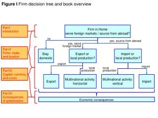
THERMAL NOISE Sources of Interference XMTR RCVR RCVR XMTR FEXT NEXT RCVR XMTR XMTR RCVR RF INGRESS
Interference for xDSL ISDN DSL AM BROADCASTRADIO THERMAL NOISE
Unger’s discovery What happens with multiple sources of cross-talk? Unger (Bellcore) : 1% worst case NEXT (T1D1.3 185-244) • 50 pair binders • 22 gauge PIC • 18 Kft Found empirically that cross-talk only increases as N0.6 This is because extra interferers must be further away
NEXT Only close points are important • Distant points twice attenuated by line |H(f,x)|2 Unger dependence on number of interferers Frequency dependence • Transfer function ~ I2Campbell / R ~ f2 / f1/2= f3/2 • Power spectrum of transmission Total NEXT interference (noise power) KNEXT N0.6 f3/2 PSD(f)
FEXT Entire parallel distance important • Thus there will be a linear dependence on L Unger dependence on number of interferers Frequency dependence • Transfer function ~ I2Campbell ~ f2 • Power spectrum of transmission Total FEXT interference (noise power) KFEXT N0.6 L f2 |Hchannel(f)|2 PSD(f)
What do we do now? We now know the loss and the interference We have all the needed ingredients The time has come to learn what to do with them! Once again the breakthrough came from Bell Labs …
Shannon - Game plan Claude Shannon (Bell Labs) 1948 No loss in going to digital communications • All information can be converted to bits • Source channel separation theorem • Source encoding theorems • Channel capacity theorems • All information should be converted to bits
Shannon - SeparationTheorem Source channel separation theorem • Separate source coding from channel coding • No efficiency loss The following are NOT optimal !!! • OSI layers • Separation of line code from ECC
Shannon - Channel Capacity Every bandlimited noisy channel has a capacity Below capacity errorless information reception Above capacity errors Shocking news to analog engineers Previously thought: only increasing power decreases error rate But Shannon didn’t explain HOW!
Channel Capacity (continued) Shannon’s channel capacity theorem: If no noise (even if narrow BW): Infinite information transferred instantaneously Just send very precise level If infinite bandwidth (even if high noise): No limitation on how fast switch between bits If both limitations: C = BW log2 ( SNR + 1 )
Channel Capacity (continued) The forgotten part: All correlations introduce redundancy Maximal information means nonredundant The signal that attains channel capacity looks like white noise filtered to the BW
Channel Capacity (continued) That was for an ideal low-pass channel What about a real channel (like DSL)? Shannon says ... Simply divide channel into subchannels and integrate