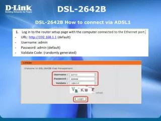
x DSL Introduction
x DSL Introduction . Yaakov J. Stein Chief Scientist RAD Data Communications. PSTN wiring. subscriber line. subscriber line. Old (analog) PSTN. UTP. Voice-grade modems. modem. modem. New (digital) PSTN. CO SWITCH. “last mile”. TDM. analog. digital. PSTN. TDM.

x DSL Introduction
E N D
Presentation Transcript
xDSLIntroduction Yaakov J. Stein Chief ScientistRAD Data Communications
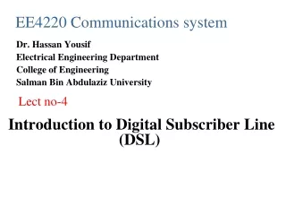
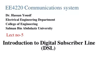
subscriber line subscriber line Old (analog) PSTN
UTP Voice-grade modems modem modem
New (digital) PSTN CO SWITCH “last mile” TDM analog digital PSTN TDM “last mile” CO SWITCH
network/ ISP router Voice-grade modems over new PSTN CO SWITCH PSTN UTP subscriber line modem CO SWITCH modem Modem technology is basically unchanged Communications speeds do not increase
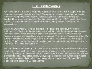
What is UTP? • Two plastic insulated copper wires • Two directions over single pair • Twisted to reduce crosstalk • Supplies DC power and audio signal • Due to physics attenuation increases with frequency
Why twisted? from Bell’s 1881 patent To place the direct and return lines close together. To twist the direct and return lines around one another so that they should be absolutely equidistant from the disturbing wires n a V = (a+n) - (b+n) b
Why twisted? - continued But even UTP has some cross-talk George Cambell models UTP crosstalk (see BSTJ 14(4) Oct 1935) Cross-talk due to capacitive and/or inductive mismatch |I2| = Q f V1where Q ~ (Cbc-Cbd) or Q~(Lbc-Lad)
Loading coil What does a loading coil do? Flattens response in voice band Attenuates strongly above voice frequencies loops longer than 18 Kft need loading coils 88 mH every 6kft starting 3kft
Bridge taps I forgot to mention bridged taps! Parallel run of unterminated UTP • unused piece left over from old installation • placed for subscriber flexibility Signal are reflected from end of a BT A bridged tap can act like a notch filter!
Other problems Subscriber lines are seldom single runs of cable US UTP usually comes in 500 ft lengths Splices must be made Average line has >20 splices Splices corrode and add to attenuation Gauge changes Binders typically 26 AWG Change to 24 after 10 Kft In rural areas change to 19 AWG after that
CSA guidelines 1981 AT&T Carrier Service Area guidelines • No loading coils • Maximum of 9 Kft of 26 gauge (including bridged taps) • Maximum of 12 Kft of 24 gauge (including bridged taps) • Maximum of 2.5 Kft bridged taps • Maximum single bridged tap 2 Kft • Suggested: no more than 2 gauges In 1991 more than 60% of US lines met CSA requirements
Present US PSTN UTP only in the last mile (subscriber line) • 70% unloaded < 18Kft • 15% loaded > 18Kft • 15% optical or digital to remote terminal + DA (distribution area) PIC, 19, 22, 24, 26 gauge Built for 2W 4 KHz audio bandwidth DC used for powering Above 100KHz: • severe attenuation • cross-talk in binder groups (25 - 1000 UTP) • lack of intermanufacturer consistency
Alternatives for data services Fiber, coax, HFC COST: $10K-$20K / mile TIME: months to install T1/E1 COST: >$5K/mile for conditioning TIME: weeks to install DSL COST: @ 0 (just equipment price) TIME: @ 0 (just setup time)
xDSL Need higher speed digital connection to subscribers Not feasible to replace UTP in the last mile Older voice grade modems assume 4KHz analog line Newer (V.90) modems assume 64Kbps digital line DSL modems don’t assume anything Use whatever the physics of the UTP allows
Analog modem CO SWITCH PSTN POTS-C POTS-R network/ UTP ISP POTS POTS PDN SPLITTER SPLITTER DSLAM xTU-R router WAN xTU-C x = H, A, V, ... xDSL System Reference Model
Splitter Splitter separates POTS from DSL signals • Must guarantee lifeline POTS services! • Hence usually passive filter • Must block impulse noise (e.g. ring) from phone into DSL ADSLforum/T1E1.4 specify that splitter be separate from modem No interface specification yet (can’t buy splitter and modem from different vendors) Splitter requires installation • Costly technician visit is the major impediment to deployment • G.lite is splitterless ADSL
N S Why is DSL better than a voice-grade modem? • Analog telephony modems are limited to 4 KHz bandwidth • Shannon’s theorem tells us that the maximum transfer rate for SNR >> 1 C = BW log2 ( SNR + 1 ) C(bits/Hz) = SNR(dB) / 3 So by using more BW we can get higher transfer rates! But what is the BW of UTP?
Maximum reach • Length of cable for reliable communications ASSUMING ONLY THERMAL NOISE Bellcore study in residential areas (NJ) found • -140 dBm / Hz • white (i.e. independent of frequency) is a good approximation • Real systems have other sources of noise, and thus have lower reach (Shannon!) • We can compute the maximum reach from UTP attenuation
THERMAL NOISE Sources of Interference XMTR RCVR RCVR XMTR FEXT NEXT RCVR XMTR XMTR RCVR RF INGRESS
Examples of Realistic Reach More realistic design goals (splices, some xtalk) • 1.5 Mbps 18 Kft 5.5 km (80% US loops) • 2 Mbps 16 Kft 5 km • 6 Mbps 12 Kft 3.5 km (CSA 50% US loops) • 10 Mbps 7 Kft 2 km • 13 Mbps 4.5 Kft 1.4 km • 26 Mbps 3 Kft 900 m • 52 Mbps 1 Kft 300 m (SONET STS-1 = 1/3 STM-1)
ITU G.99x standards • G.991 HDSL (G.991.1 HDSL G.991.2 SHDSL) • G.992 ADSL (G.992.1 ADSL G.992.2 splitterless ADSL G.992.3 ADSL2 G.992.4 splitterless ADSL2 G.992.5 ADSL2+) • G.993 VDSL (G.993.1 VDSL G.993.2 VDSL2) • G.994 HANDSHAKE • G.995 GENERAL (INFO) • G.996 TEST • G.997 PLOAM • G.998 bonding (G.998.1 ATM G.998.2 Ethernet G.998.3 TDIM)
Bonding If we need more BW than attainable by Shannon bounds we can use more than one UTP pair (although XT may reduce) this is called bonding or inverse multiplexing There are many ways of using multiple pairs: • ATM - extension of IMA (may be different rates per pair) cells marked with SID and sent on any pair • Ethernet - based on 802.3(EFM) frames are fragmented, marked with SN, and sent on many pairs • Time division inverse mux • Dynamic Spectral Management (Cioffi) • Ethernet link aggregation
T1 service 1963: Coax deployment of T1 • 2 groups in digital TDM • RZ-AMI line code • Beyond CSA range should use DLC (direct loop carrier) • Repeaters every 6 Kft • Made possible by Bell Labs invention of the transistor 1971: UTP deployment of T1 • Bring 1.544 Mbps to customer private lines • Use two UTP in half duplex • Requires expensive line conditioning • One T1 per binder group
T1 line conditioning In order for a subscriber’s line to carry T1 • Single gauge • CSA range • No loading coils • No bridged taps • Repeaters every 6 Kft (starting 3 Kft) • One T1 per binder group • Labor intensive (expensive) process • Need something better … (DSL) • Europeans already found something better
The first xDSL! 1984,88: IDSL • BRI access for ISDN • 2B1Q (4 level PAM) modulation • Prevalent in Europe, never really caught on in US • 144 Kbps over CSA range 1991: HDSL • Replace T1 line code with IDSL line code (2B1Q) • 1 UTP (3 in Europe for E1 rates) • Full CSA distance without line conditioning • Requires DSP
HDSL Replace T1/E1 DS1 service Use 2B1Q line code, DFE Full duplex on each pair with echo cancellation CSA reach w/o conditioning/repeaters more complex DSP ANSI: 2 pairs for T1 (each 784 Kbps) ETSI: 1, 2, 3 or 4 pairs Most mature of DSL technologies
HDSL2 Customers request HDSL service that is • single UTP HDSL • at least full CSA reach • spectrally compatible w/ HDSL, T1, ADSL, etc. Variously called HDSL2 (ANSI) SDSLSymmetricDSL (ETSI) Now called SHDSL Single pairHDSL (ITU)
ADSL (full rate) Asymmetric - high rate DS lower rate US Originally designed forvideo on demand Almost retired due to lack of interest …but then came the Internet Studies show DS:US should be about 10:1 full rate ADSL 512-640 kbps US, 6-8 Mbps DS G.lite 512 Kbps US, 1.5 Mbps DS ADSLcould meanAll Data Subscribers Living
G.lite Splitterless ADSL, UAWG ADSL compatible DMT compatible using only 128 tones 512 Kbps US / 1.5 Mbps DS Still much faster than V.34 or V.90 modems No splitter required! Certain features removed for simplicity simpler implementation (only 500 MIPS < 2000 MIPS for full rate)
ADSL2 ADSL uses BW from 20 kHz to 1.1 MHz ADSL2 Increases rate/reach of ADSL by using 20 kHz - 4.4 MHz Also numerous efficiency improvements • better modulation • reduced framing overhead • stronger ECC • reduced power mode • misc. algorithmic improvements for given rate, reach improved by 200 m 3 user data types - STM, ATM and packet (Ethernet) ADSL2+ dramatically increased rate at short distances
VDSL Optical network expanding (getting closer to subscriber) Optical Network Unit ONU at curb or basement cabinet FTTC (curb), FTTB (building) These scenarios usually dictates low power Rates can be very high since required reach is minimal! Proposed standard has multiple rates and reaches
VDSL2 VDSL uses BW of 1.1 MHz - 12 MHz (spectrally compatible with ADSL) VDSL2 uses 20 KHz - 30 MHz • new band-plans • increased DS transmit power • various algorithmic improvements • borrowed improvements from ADSL2 • 3 user data types - STM, ATM and packet (pure Ethernet)
HPNA (G.PNT) • Studies show that about 50% of US homes have a PC 30% have Internet access, 20% have more than one PC! • Average consumer has trouble with cabling HomePNA de facto industry standard for home networking • Computers, peripherals interconnect (and connect to Internet?) using internal phone wiring (user side of splitter) • Does not interrupt lifeline POTS services • Does not require costly or messy LAN wiring of the home • Presently 1 Mbps, soon 10 Mbps, eventually 100 Mbps!
Competition - Cable modems CABLE MODEM CMTS CABLE MODEM OPTICAL FIBER NODE CATV HEADEND fiber coax COAXIAL AMPLIFIER CABLE MODEM CABLE MODEM
How do modems work? The simplest attempt is to simply transmit 1 or 0 (volts?) This is called NRZ (short serial cables, e.g. RS232) Information rate = number of bits transmitted per second (bps)
The simplest modem - DC So what about transmitting -1/+1? This is better, but not perfect! • DC isn’t exactly zero • Still can have a long run of +1 OR -1 that will decay • Even without decay, long runs ruin timing recovery (see below)
The simplest modem - DC What about RZ? • No long +1 runs, so DC decay not important • Still there is DC • Half width pulses means twice bandwidth!
The simplest modem - DC T1 uses AMI (Alternate Mark Inversion) • Absolutely no DC! • No bandwidth increase!
The simplest modem - DC Even better - use OOK (On Off Keying) • Absolutely no DC! • Based on sinusoid (“carrier”) • Can hear it (morse code)