Download
1 / 11
110 likes | 367 Views
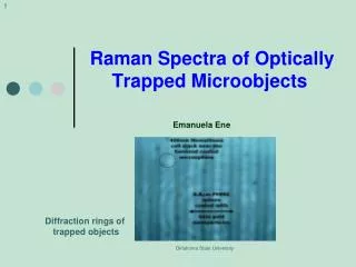
Near-field Raman imaging using optically trapped dielectric microsphere. Johnson Kasim et.al. Optics Express(2008) . Outline. Introduction To overcome the diffraction limit Raman spectroscopy Experiment Setup Results C onclusion. To overcome the diffraction limit.

E N D
Near-field Raman imaging using optically trapped dielectric microsphere Johnson Kasimet.al. Optics Express(2008)
Outline • Introduction • To overcome the diffraction limit • Raman spectroscopy • Experiment Setup • Results • Conclusion
To overcome the diffraction limit • Going through particles with light • Injecting light stop on sample Light spot ~100 nm Scattering light Particle 1 Particle 2 Sample Resolution (~wavelength/2) Resolution (~light spot)
Advanced point the method • Simply to deliver the laser light by fiber • Fiber is keep at a close distance(~tens nm) • Very low laser power(typically 100nW) • Taking a long time(e.q.~10hours) • By using optical tweezers mechanism • The laser is focused to a spot smaller than above method • Taking a short time(e.q.~10minutes)
Experiment Setup o Spot size
Conclusion • Report a new design in performing high-resolution near-field Raman imaging • Scanning a 3µm diameter polystyrene microsphere using optical tweezers mechanism • Laser spot size (84nm) • Reducing laser spot size about (48nm by using a 0.5µm diameter polystyrene microsphere • If we reduce brownian motion effect ,obtain better small resolution.
Timetable • Mechanical setup • Beam alignment • Test tapping force • Galvanometer control by function generator • Tracking laser setup • Connect QPD to OT301 • Connect computer to SR830 • GPID card • Convert Adapter(RS232)