Download
1 / 35
350 likes | 546 Views
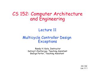
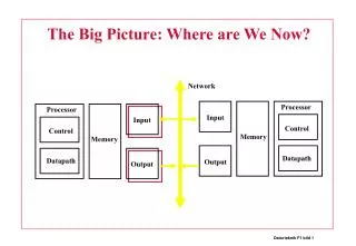
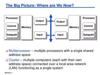
CS 152 Computer Architecture and Engineering Lecture 11 Multicycle Controller Design (Continued) . Processor. Input. Control. Memory. Datapath. Output. The Big Picture: Where are We Now? . The Five Classic Components of a Computer Today’s Topics: Microprogramed control Administrivia

E N D
CS 152 Computer Architecture and EngineeringLecture 11Multicycle Controller Design (Continued)
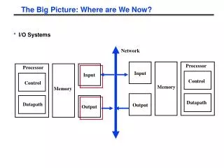
Processor Input Control Memory Datapath Output The Big Picture: Where are We Now? • The Five Classic Components of a Computer • Today’s Topics: • Microprogramed control • Administrivia • Microprogram it yourself • Exceptions
sequencer control datapath control microinstruction micro-PC sequencer Controller Design • The state digrams that arise define the controller for an instruction set processor are highly structured • Use this structure to construct a simple “microsequencer” • Control reduces to programming this very simple device microprogramming
MemToReg RegWr RegDst MemRd MemWr ALUctr ALUSrc ExtOp Reg. File Ext ALU S Mem Access M Data Mem Result Store Multicycle Datapath Equal nPC_sel E Reg File A PC IR Next PC B Instruction Fetch Operand Fetch
Execute Memory Write-back State Diagram of Controller “instruction fetch” IR <= MEM[PC] 0000 “decode” A <= R[rs] B <= R[rt] 0001 LW R-type ORi SW BEQ PC <= Next(PC) S <= A fun B S <= A or ZX S <= A + SX S <= A + SX 0100 0110 1000 1011 0011 M <= MEM[S] MEM[S] <= B PC <= PC + 4 1001 1100 R[rd] <= S PC <= PC + 4 R[rt] <= S PC <= PC + 4 R[rt] <= M PC <= PC + 4 0101 0111 1010
Execute Memory Write-back Using a Jump Counter “instruction fetch” IR <= MEM[PC] 0000 inc “decode” A <= R[rs] B <= R[rt] 0001 load LW R-type ORi SW BEQ PC <= Next(PC) S <= A fun B S <= A or ZX S <= A + SX S <= A + SX 0100 0110 1000 1011 0011 inc inc inc inc zero M <= MEM[S] MEM[S] <= B PC <= PC + 4 1001 1100 inc R[rd] <= S PC <= PC + 4 R[rt] <= S PC <= PC + 4 R[rt] <= M PC <= PC + 4 zero 0101 0111 1010 zero zero zero
Example: Jump-Counter i i 0000 i+1 Map ROM None of above: Do nothing (for wait states) op-code zero inc load Counter
Sequencer • Sequencer-based control unit • Called “microPC” or “µPC” vs. state register Control Value Effect00 Next µaddress = 0 01 Next µaddress = dispatch ROM 10 Next µaddress = µaddress + 1 Dispatch ROM: Microprogram 1 microPC Adder Opcode Dispatch State R-type 000000 0100 BEQ 000100 0011 ori 001101 0110 LW 100011 1000 SW 101011 1011 Mux 2 1 0 0 µAddress Select Logic Dispatch ROM Opcode
Microprogramming (Maurice Wilkes) • Control is the hard part of processor design ° Datapath is fairly regular and well-organized ° Memory is highly regular ° Control is irregular and global Microprogramming: -- A Particular Strategy for Implementing the Control Unit of a processor by "programming" at the level of register transfer operations Microarchitecture: -- Logical structure and functional capabilities of the hardware as seen by the microprogrammer Historical Note: IBM 360 Series first to distinguish between architecture & organization Same instruction set across wide range of implementations, each with different cost/performance
“Macro and micro - instruction” Interpretation User program plus Data this can change! Main Memory ADD SUB AND . . . one of these is mapped into one of these DATA execution unit AND microsequence e.g., Fetch Calc Operand Addr Fetch Operand(s) Calculate Save Answer(s) CPU control memory
Variations on Microprogramming ° “Horizontal” Microcode – control field for each control point in the machine ° “Vertical” Microcode – compact microinstruction format for each class of microoperation – local decode to generate all control points (remember ALU?) branch: µseq-op µadd execute: ALU-op A,B,R memory: mem-op S, D µseq µaddr A-mux B-mux bus enables register enables Horizontal Vertical
Extreme Horizontal 3 1 input select . . . N3 N2 N1 N0 1 bit for each loadable register enbMAR enbAC . . . Incr PC ALU control Depending on bus organization, many potential control combinations simply wrong, i.e., implies transfers that can never happen at the same time. Makes sense to encode fields to save ROM space Example: mem_to_reg and ALU_to_reg should never happen simultaneously; => encode in single bit which is decoded rather than two separate bits NOTE:the encoding should be only wide enough so that parallel actions that the datapath supports should still be specifiable in a single microinstruction
More Vertical Format next states inputs src dst other control fields MUX D E C D E C Multiformat Microcode: 6 1 3 Branch Jump 0 cond next address 1 3 3 3 1 dst src alu Register Xfer Operation D E C D E C
Hybrid Control Not all critical control information is derived from control logic E.g., Instruction Register (IR) contains useful control information, such as register sources, destinations, opcodes, etc. enable signals from control Register File R S 1 D E C R S 2 D E C R D D E C rs1 IR op rs2 rd to control
Summary: Horizontal vs. Vertical Microprogramming NOTE: previous organization is not TRUE horizontal microprogramming; register decoders give flavor of encoded microoperations Most microprogramming-based controllers vary between: horizontal organization (1 control bit per control point) vertical organization (fields encoded in the control memory and must be decoded to control something) Vertical + easier to program, not very different from programming a RISC machine in assembly language - extra level of decoding may slow the machine down Horizontal + more control over the potential parallelism of operations in the datapath - uses up lots of control store
Microprogramming a multicycle processor • 1) Choose datapath and sequencer architecture • 2) Assign states and sequence of each (multicycle) instruction (i.e. define the controller FSM) • 2) Choose microinstruction format (minimum bits to describe all allowable functions of sequencer and datapath) • 3) Map instructions into microinstruction sequences
Sequencer • Sequencer-based control unit • Called “microPC” or “µPC” vs. state register Control Value Effect00 Next µaddress = 0 01 Next µaddress = dispatch ROM 10 Next µaddress = µaddress + 1 Dispatch ROM: Microprogram 1 microPC Adder Opcode Dispatch State R-type 000000 0100 BEQ 000100 0011 ori 001101 0110 LW 100011 1000 SW 101011 1011 Mux 2 1 0 0 µAddress Select Logic Dispatch ROM Opcode
32 0 Mux 0 Mux 1 Instruction Reg 32 ALU Out 0 1 Mux 32 32 1 ALU Control Mux 1 0 << 2 Extend 16 Datapath – single memory, single regfile PCWr PCWrCond PCSrc • Miminizes Hardware: 1 memory, 1 adder Zero ALUSelA IorD MemWr IRWr RegDst RegWr 1 Mux 32 PC 0 Zero 32 Rs Ra 32 RAdr 5 32 Rt 32 Rb busA A ALU Ideal Memory 32 Reg File 5 4 Rt 0 Rw 32 WrAdr 32 B 1 32 Rd Mem Data Reg Din Dout busW busB 2 32 3 Imm 32 ALUOp ExtOp MemtoReg ALUSelB
Finite State Machine (FSM) Spec IR <= MEM[PC] PC <= PC + 4 “instruction fetch” 0000 “decode” Q: What can we do in state 0001? 0001 LW BEQ R-type ORi SW ALUout <= A fun B ALUout <= A or ZX ALUout <= A + SX ALUout <= A + SX ALUout <= PC +SX Execute 0100 0110 1000 1011 0010 M <= MEM[ALUout] MEM[ALUout] <= B Memory If A = B then PC <= ALUout 1001 1100 0011 R[rd] <= ALUout R[rt] <= ALUout R[rt] <= M Write-back 0101 0111 1010
Finite State Machine (FSM) Spec (improved) IR <= MEM[PC] PC <= PC + 4 “instruction fetch” 0000 ALUout <= PC +SX “decode” 0001 LW BEQ R-type ORi SW ALUout <= A fun B ALUout <= A or ZX ALUout <= A + SX ALUout <= A + SX If A = B then PC <= ALUout Execute 0100 0110 1000 1011 0010 M <= MEM[ALUout] MEM[ALUout] <= B Memory 1001 1100 R[rd] <= ALUout R[rt] <= ALUout R[rt] <= M Write-back 0101 0111 1010
Designing a Microinstruction Set 1) Start with list of control signals 2) Group signals together that make sense (vs. random): called “fields” 3) Place fields in some logical order (e.g., ALU operation & ALU operands first and microinstruction sequencing last) 4) Create a symbolic legend for the microinstruction format, showing name of field values and how they set the control signals 5) To minimize the width, encode operations that will never be used at the same time
1) Start with list of control signals Signal name Effect when deasserted Effect when assertedALUSelA 1st ALU operand = PC 1st ALU operand = Reg[rs]RegWr None Reg. is written MemtoReg Reg. write data input = ALU Reg. write data input = memory RegDst Reg. dest. no. = rt Reg. dest. no. = rdMemRd None Memory at address is read, MemWr None Memory at address is written IorD Memory address = PC Memory address = SIRWr None IR <= MemoryPCWr None PC <= PCSourcePCWrCond None IF ALUzero then PC <= PCSourcePCSrc PCSource = ALU PCSource = ALUoutExtOp Zero Extended Sign Extended Single Bit Control Signal name Value EffectALUOp 00 ALU adds 01 ALU subtracts 10 ALU does function code 11 ALU does logical OR ALUSelB 00 2nd ALU input = 4 01 2nd ALU input = Reg[rt] 10 2nd ALU input = extended,shift left 2 11 2nd ALU input = extended Multiple Bit Control
32 0 Mux 0 Mux 1 Instruction Reg 32 ALU Out 0 1 Mux 32 32 1 ALU Control Mux 1 0 << 2 Extend 16 2) Group into fields of unrelated signals PCWrite PCWr PCWrCond PCSrc • Miminizes Hardware: 1 memory, 1 adder SRC1 Zero ALUSelA IorD MemWr IRWr RegDst RegWr 1 Mux 32 PC 0 Zero 32 Rs Ra 32 RAdr 5 32 Rt 32 Rb busA A ALU Ideal Memory 32 Reg File 5 4 Rt 0 Rw 32 WrAdr 32 B 1 32 Rd Mem Data Reg Din Dout busW busB 2 32 3 MemRd ALU Imm 32 ALUOp ExtOp MemtoReg ALUSelB SRC2
2,3 & 4 ) Group into fields, order and assign names Field Name Values for Field Function of Field with Specific ValueALU Add ALU adds Subt. ALU subtracts Func ALU does function code Or ALU does logical ORSRC1 PC 1st ALU input <= PC rs 1st ALU input <= Reg[rs]SRC2 4 2nd ALU input <= 4 Extend 2nd ALU input <= sign ext. IR[15-0] Extend0 2nd ALU input <= zero ext. IR[15-0] Extshft 2nd ALU input <= sign ex., sl IR[15-0] rt 2nd ALU input <= Reg[rt]dest(ination) rd ALU Reg[rd] <= ALUout rt ALU Reg[rt] <= ALUout rt Mem Reg[rt] <= Mem Mem(ory) Read PC Read memory using PC Read ALU Read memory using ALUout for addr Write ALU Write memory using ALUout for addrMemreg IR IR <= MemPCwrite PCwr PC <= PCSource PCSrc IF Zero then PCSource <= ALUout else ALU PCWrCond IF Zero then PC <= PCSource Seq(uencing) Seq Go to sequential µinstruction Fetch Go to the first microinstruction Dispatch Dispatch using ROM.
5) Encode each field Field Name Width Control Signals Set wide narrow ALU 4 2 ALUOp SRC1 2 1 ALUSelA SRC2 5 3 ALUSelB, ExtOp Dest 3 2 RegWrite, MemtoReg, RegDst Mem 3 2 MemRd, MemWre, IorD Memreg 1 1 IRWrite PCWrite 3 1 PCWr, PCSrc, PCWrCond Seq 3 2 AddrCtl Total width 24 14 bits
5) Encode each field (cont.) Dest: CodeName RegWrite MemToReg RegDest 00 --- 0 X X 01 rd ALU 1 0 1 10 rt ALU 1 0 0 11 rt MEM 1 1 0 SRC2: Code Name ALUSelB ExtOp 000 --- X X 001 4 00 X 010 rt 01 X 011 ExtShft 10 1 100 Extend 11 1 111 Extend0 11 0
Finally – Do the microprogram…. 0000 0001 0100 0101 0110 0111 1000 1001 1010 1011 1100 0010 Label ALU SRC1 SRC2 Dest. Memory MemReg. PCWrite Seq Fetch: Add PC 4 Read PC IR PCwr Seq Add PC Extshft Dispatch Rtype: Func rs rt Seq rd ALU Fetch Ori: Or rs Extend0 Seq rt ALU Fetch Lw: Add rs Extend Seq Read ALU Seq rt MEM Fetch Sw: Add rs Extend Seq Write ALU Fetch Beq: Subt. rs rt PCWrCond. Fetch
Microprogramming Pros and Cons • Ease of design • Flexibility • Easy to adapt to changes in organization, timing, technology • Can make changes late in design cycle, or even in the field • Can implement very powerful instruction sets (just more control memory) • Generality • Can implement multiple instruction sets on same machine. • Can tailor instruction set to application. • Compatibility • Many organizations, same instruction set • Costly to implement • Slow
Adding a more complex memory model PC addr InstMem_rd Instruction Memory IM_wait data Inst. Reg IR_en Add a wait flag of indeterminate length – IM_wait (due to caching)
Execute Memory Write-back Controller handles non-ideal memory “instruction fetch” IR <= MEM[PC] IMwait ~IMwait “decode / operand fetch” A <= R[rs] B <= R[rt] LW R-type ORi SW BEQ PC <= Next(PC) S <= A fun B S <= A or ZX S <= A + SX S <= A + SX M <= MEM[S] MEM[S] <= B ~wait wait wait ~wait R[rd] <= S PC <= PC + 4 R[rt] <= S PC <= PC + 4 R[rt] <= M PC <= PC + 4 PC <= PC + 4
Really Simple Time-State Control IR <= MEM[PC] instruction fetch IMwait ~IMwait A <= R[rs] B <= R[rt] decode LW R-type ORi SW BEQ Execute S <= A fun B S <= A or ZX S <= A + SX S <= A + SX Memory M <= MEM[S] MEM[S] <= B wait wait R[rd] <= S PC <= PC + 4 R[rt] <= S PC <= PC + 4 R[rt] <= M PC <= PC + 4 PC <= Next(PC) write-back PC <= PC + 4
A S B M Time-state Control Path • Local decode and control at each stage Valid IRex IR IRwb Inst. Mem IRmem WB Ctrl Dcd Ctrl Ex Ctrl Mem Ctrl Equal Reg. File Reg File Exec PC Next PC Mem Access Data Mem
Overview of Control • Control may be designed using one of several initial representations. The choice of sequence control, and how logic is represented, can then be determined independently; the control can then be implemented with one of several methods using a structured logic technique. Initial Representation Finite State Diagram Microprogram Sequencing Control Explicit Next State Microprogram counter Function + Dispatch ROMs Logic Representation Logic Equations Truth Tables Implementation PLA ROM Technique “hardwired control” “microprogrammed control”
Summary • Specialize state-diagrams easily captured by microsequencer • simple increment & “branch” fields • datapath control fields • Most microprogramming-based controllers vary between: • horizontal organization (1 control bit per control point) • vertical organization (fields encoded in the control memory and must be decoded to control something) • Steps: • identify control signals, group them, develop “mini language”, then microprogram • Control design reduces to Microprogramming • Arbitrarily complicated instructions possible
Summary: Microprogramming one inspiration for RISC • If simple instruction could execute at very high clock rate… • If you could even write compilers to produce microinstructions… • If most programs use simple instructions and addressing modes… • If microcode is kept in RAM instead of ROM so as to fix bugs … • If same memory used for control memory could be used instead as cache for “macroinstructions”… • Then why not skip instruction interpretation by a microprogram and simply compile directly into lowest language of machine?