Download
1 / 16
160 likes | 310 Views
V3. CSC ROD Replacement Conceptual Design Review New ROD Complex (NRC) Overview & Physical D esign Michael Huffer, mehsys@slac.stanford.edu SLAC National Accelerator Lab CERN, October, 8, 2012. Representing : Rainer Bartoldus (SLAC ) Richard Claus (SLAC) Anthony DiFranzo (UCI)

E N D
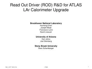
V3 CSC ROD Replacement Conceptual Design Review New ROD Complex (NRC) Overview & Physical Design Michael Huffer, mehsys@slac.stanford.edu SLAC National Accelerator Lab CERN, October, 8, 2012 Representing: Rainer Bartoldus (SLAC) Richard Claus (SLAC) Anthony DiFranzo (UCI) Raul Murillo Garcia (UCI) Nicoletta Garelli (SLAC) Ryan T. Herbst (SLAC) Andrew J. Lankford (UCI) Andrew Nelson (UCI) James Russell (SLAC) Michael Schernau (UCI) Su Dong (SLAC)
The NRC (New ROD Complex) • Overview • The NRC as a physical object & its interfaces • The NRC’s ATCA (Advanced TeleCommunication Architecture) shelf • Choice + power + management • The NRC’s ATCA Front-Board (the COB, Cluster-On-Board) • The COB’s RCEs (Reconfigurable-Cluster-Element) • Concepts and implementation (the mezzanine board) • The RCE’s Protocol-Plug-Ins • The RCE’s CE (Cluster-Element) • The CE’s software services • The NRC’s ATCA RTMs (Rear-Transition Modules) • One RTM for on-detector-electronics (The CSC RTM) • One RTM for the ROS (The SFP RTM) • Development & installation • Long term maintenance • Summary
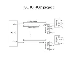
The NRC (physical) block diagram & interfaces… • ATCA shelf • Full mesh fabric (10GE) • Dual-star base (TTC & busy) • 5 Front-Boards (COB) • Differentiated only by firmware/software • 4 FEX boards (rcvs input & FEX) • 1 Formatter board (Formats events, sends to ROS) • 5 RTMs • 4 CSC (8 rcv + 4 xmt SNAP-12) • 1 SFP (16 transceivers) • Shelf power supply • + 48 VDC • Control Processor • A commodity, rack-mounted PC • Hosts TDAQ interfaces
NRC ATCA shelf • The boards used by the NRC are PICMG 3.0 compliant… • Will (co)operate in any ATCA shelf • We are mostly, if not entirely, agnostic on shelf choice, including… • Orientation (horizontal or vertical) • Airflowdirection (up/down, front/back or left/right) • Power supplied either internally or externally • Minimum shelf requirements: • Five (5) or more slots • Power and cooling for up to 1.5 Kilowatts • Full-mesh backplane • Access (through Ethernet) to its Shelf Manager • In all other shelf requirements we will be guided by ATLAS • Baseline assumes (but does not require) external power • We believe that maps best to current DCS model, however… • In terms of shelf monitoring/control we will be guided by DCS
The COB (Cluster-On-Board) • Is an ATCA Front-Board which is both carrier and interconnect • Bays hold mezzanineboards which contain RCEs • Two types of bays (Data Transport/Data Processing Module) • One DTM. Contains IPM Controller and one RCE • IPMC interacts with Shelf Manager (purpose built IPMC) • DTM RCE manages the two interconnects described below • Four DPMs. Contain 2 RCEs, each managing data from an RTM • Those RCEs provide FEX and Formatter function • Interconnects enable communication between RCEs (both inter & intra) • Two independent interconnects fabric and base • Fabric switches 10G-Ethernet to & from: • Bays, other boards (P2) & Front-Panel (SFP+) (shelf external) • Base fans outTTC and fans inBUSY to & from: • Bays, other boards (P2), & FTM (shelf external) • NRC specific • Trivial implementation, uses commodity clock fan-out buffers
Block diagram of the COB (Cluster-On-Board) 30 differential pairs/bay RTM connection Command & Control paths
Preproduction COB FTM + Base-Board IPM Controller (IPMC) DTM bay Zone 2 DPM bay (1 of 4) Zone 1 (power) Zone 3 (PICMG 3.8) • Differences between pre and production COB • Move SFP+ from RTM to Front-Board • Move IPMC onto DTM • Break up FTM into two different boards • Move resulting base-board next to P2 8 SFP+ RTM
The RCE (Reconfigurable-Cluster-Element) • Employs System-On-Chip (SoC) technology (Xilinx Virtex-5-FX) • Neither FPGA, processor, or DSP (its all three) • Contains both soft (programmable) and hard (resources)silicon. • Silicon partitioned between: • System logic or CE (Cluster-Element) • Reserves the processor resource • Interfaces with DDR3 RAM and micro-SD flash • User logic or application specific Protocol-Plug-Ins • 2 RCEs are realized as mezzanine board which plugs into a COB’s bays SO-DIMM (DDR3) SOC MICRO-SD
The Protocol-Plug-In (PPI) • Application specific firmware which communicates with the CE • May use either or both soft and hard silicon • Interact external or internal to the SOC • Interface model is the plug & socket: • A protocol is arbitrary, application-specific logic • A protocol is wrapped with predefined system logic (the Plug) • The combination of a protocol and its plug is a PPI • CE contains a set of predefined Sockets • PPIs plug into sockets to enable communication • The Implementation of the NRC is almost entirely within its PPIs… • The InputPPI, receives data from the CSC’s ASM-IIs • The TTC (Rx) PPI, decodes TTC and produces clock and L1A • The FEX PPI, produces hit channels from chamber’s data • The ROL PPI, transmits data to the ROS
The CE (Cluster-Element) • For data sent and received by its PPIs, the CE serves as: • A nexus for that data • A platform for the software which supervises its flow • Its the platform executing the NRC’s application-specific software • Feature extraction on one COB & formatting on another • It’s a CPU: • 4 Gbytes of DDR3 RAM @ 5 Gbytes/sec • 475 MHZ, PowerPC 440 • Separate 32 Kbyte instruction and data caches • APU (128-bit) interface to PPI sockets (instruction extension)
CE Software Services • Generic Bootstrap loader (For the NRC, boots RTEMS) • O/S (RTEMS) • Multi-tasking R/T kernel • POSIX compliant interfaces • Open Source • Persistency & file systems (SD-flash code & data (FAT-16)) • Networking • Full TCP/IP stack (DNS, NTP, DHCP, NFS, etc.) • POSIX compliant interfaces • PPI support (For NRC’s Input, FEX and ROL drivers) • Debugging • GNU based • Both Local and remote (network) • Diagnostics (built-in self tests and diagnostics) • Development (GNU cross-development environment)
The CSC RTM (fiber connections to on-detector electronics) • Contains 8 SNAP-12 receivers + 4 SNAP-12 transmitters • Enough connections for up to 8 chambers. Each chamber: • Uses 10/12 channels of one receiver • Uses 5/12 channels of one transmitter • Uses 1/12 channels of transmitter for pulser calibration • All 5 transmit channels are driven in common using a clock fan-out • Paired with one of four FEX COBs • PIMG 3.8 connection between RTM and COB • One RCE services one chamber • It’s the only significant piece of hardware to be designed • But existing RTM serves as prototype
SFP RTM (fiber connections to ROS) • Contains four (4) SFP cages. Each cage contains four (4) SFP transceivers • Enough connections for up to 16 ROLs (Read-Out-Link) • Paired with one Formatter COB • PICMG 3.8 connection between RTM and COB • Two chambers of data are carried on one (1) ROL • One RCE services two (2) ROLs • Purchased from Detector R & D. Prototype exists (see below)
Development & installation strategy • Decouple (as much as practical) P1 needs. Plan to: • Develop (32 chamber) ASM-II emulator • Four (4) COBs (reclaim from spare pool) • Fabricate complement of CSC RTM (8 xmt, 4 rcv) • Develop trigger simulator (9th RCE on any COB) • See TTC (Tx) Plugin • Reuse existing LTPs and data simulators • Maintain parallel test-stands • SLAC, UCI & CERN (@ Building 188) • Disturb as little as possible the current complex: • Necessary to (re)commission small wheel • Allows side by side comparisons • Use adjoining rack? Stephanie Zimmermann: • “Rack space needs [for the NRC] to be found for this and details discussed with OPM" CSC rack Muon “upgrade” rack
Long-term Maintenance • SLAC’s interest in ATCA is deep and abiding • SLAC now has more five years of experience with ATCA • ATCA/COB/RCE is a long-term strategic investment for SLAC • Is and will be deployed in LCLS, LSST, LBNE, HPS, SID • Transfer experience and knowledge • One reason for UCI’s involvement • Align our (NRC) ATCA usage with ATLAS • Leverage large knowledge pool • Provide for spares and include redundancy • NRC has generous (~100 %) spares, includes redundant ShM & P/S • “Maintenance is less onerous than one might expect”: • Field personnel are not expected to understand ATCA • Complexity is in FRUs (Field-Replaceable-Units) not their shelf • FRUs are not diagnosed, they are either failed-over or replaced • Reliability was one of ATCA key requirements Markus asks: “How does one maintain a new platform standard?”:
Summary • The NRC fits into a single (5 slot) ATCA shelf • Despite change from VME to ATCA the NRC satisfies all its interfaces • CSC on-detector electronics & ROS fibers “plug in” • LTP and Busy module connections “plug in” • Partitioning & “stopless-removal” granularity remains the same • Development strategy is to depend as little as possible on P1 schedule • Before shipment to CERN, NRC tested as complete unit • Emulate entire on-detector electronics (with 4 COBs) • Installation strategy is to disturb as little as possible current complex • Simplifies (re) commissioning of the small wheel • Preserves the current complex as a reference platform • Reuse of tools developed out of Detector R & D program transform design from a hardware to a software & firmware centric-design • Shelf, Power and Control Processor are commodity items • COB & SFP RTM “purchased” from detector R & D program