Download
1 / 38
380 likes | 653 Views
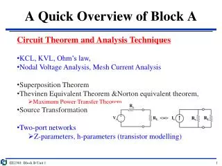
A Quick Overview of Block A. Circuit Theorem and Analysis Techniques KCL, KVL, Ohm’s law, Nodal Voltage Analysis, Mesh Current Analysis Superposition Theorem Thevinen Equivalent Theorem &Norton equivalent theorem, Maximum Power Transfer Theorem Source Transformation Two-port networks

E N D
A Quick Overview of Block A • Circuit Theorem and Analysis Techniques • KCL, KVL, Ohm’s law, • Nodal Voltage Analysis, Mesh Current Analysis • Superposition Theorem • Thevinen Equivalent Theorem &Norton equivalent theorem, • Maximum Power Transfer Theorem • Source Transformation • Two-port networks • Z-parameters, h-parameters (transistor modelling) EE2301: Block B Unit 1
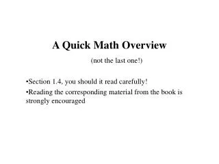
Resistors in real life High power resistors Common resistors Surface mount AC circuits - Unit 1: Transient Analysis
Block B Unit 1 outline • AC circuit components • capacitors • inductors • Key concepts when dealing with AC • Sinusoids (frequency, amplitude, phase) • Instantaneous and Average power • Phasors and Complex numbers • Impedance and Admittance G. Rizzoni, “Fundamentals of EE” Chapters 4.1, 4.2, 4.4, 7.1 EE2301: Block B Unit 1
Energy Dissipation and Storage Unlike the resistor, ideal capacitors and inductors are energy storage devices. The resistor, on the other hand, dissipates or consumes energy. Resistor Dissipates Energy (V-I is time invariant) Capacitor Inductor Store Energy (V-I is time variant) EE2301: Block B Unit 1
Circuit Elements Resistor Dissipates Energy (V-I is time invariant) Capacitor Inductor Store Energy (V-I is time variant) AC circuits - Unit 1: Transient Analysis
Capacitor and Capacitance Capacitor • A capacitor comprises 2 parallel conducting plates separated by an insulator (or dielectric) • A capacitor can store energy in the electric field when a voltage is applied across the plates + Energy stored: - Capacitance • Capacitance is a measure of the capacity of the device to store charge • Commonly symbolized by the letter (C) • Measured by the unit Farad (F) • Related to charge and voltage by: Q = CV, where V is the voltage across the capacitor and Q is the charge stored EE2301: Block B Unit 1
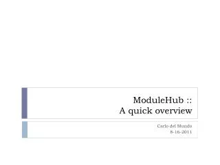
Capacitors in real life ET...\^o_o^/ ?? Surface mount Through hole AC circuits - Unit 1: Transient Analysis
Capacitor charge and discharge • Charge develops as voltage is applied • Electric field stores energy Charging occurs when a voltage difference is applied. Voltage across the capacitor is initially zero in this figure. Discharging when the voltage difference is removed. In the figures below, the voltage across the capacitor is switched to zero. EE2301: Block B Unit 1
I-V relation in a capacitor If the voltage across the capacitor is time-varying, this gives rise to a time-varying charge on the capacitor voltage to give time varying charge: + Q(t) = CV(t) V Differentiating with respect to time (t) we obtain the current: - Definitely a must to memorize! Inversely, we can likewise express the capacitor voltage in terms of its current by integrating the capacitor current: EE2301: Block B Unit 1
Capacitors in Series and Parallel The Proof: Applying KVL: v(t) = v1+v2+v3 C1 CEQ C2 C3 In Series In Parallel The Proof: Applying KCL: ic = i1 + i2 + i3 CEQ C1 C2 C3 CEQ = C1 + C2 + C3 EE2301: Block B Unit 1
Capacitor response to DC & AC • If applied voltage is a DC • Insulating dielectric blocks the current from flowing through • Plates will charge up • Capacitor acts as an open circuit for DC • If applied voltage is an AC • Charge on the plates also likewise varies in time with the AC • Capacitor therefore does not act as an open circuit in the presence of an AC EE2301: Block B Unit 1
Inductors and Inductance • Elements that have the ability to store energy in a magnetic field • Typically made by winding a coil around a core Energy stored • Inductance arises from Faraday’s law whereby an EMF (electro-motive force) is generated to oppose a change in current • Change in current causes a change in the magnetic flux • Commonly symbolized by the letter (L) • Unit for Inductance is the Henry (H) EE2301: Block B Unit 1
I-V relation in an Inductor • Inductor acts as a short circuit in the presence of DC since resistance of the wire is zero IDEALLY • But for a time-varying voltage, the voltage-current relationship is given as above From Faraday’s Law: But the flux is given by: Φ = Li Inversely, we can likewise express the inductor current in terms of the voltage across it by integrating the inductor voltage: EE2301: Block B Unit 1
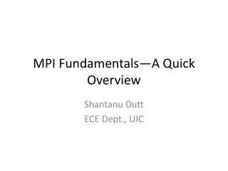
Inductors in real life AC circuits - Unit 1: Transient Analysis
Inductors in Series and Parallel Proof Applying KVL: v(t) = v1 + v2 + v3 LEQ = L1 + L2 +L3 L1 L2 LEQ L3 In Series In Parallel Proof Apply KCL: i = i1 + i2 +i3 LEQ EE2301: Block B Unit 1
Which is which? Typical printed-circuit boards AC circuits - Unit 1: Transient Analysis
Summary of Five Basic Laws • Kirchhoff’s Current Laws • Kirchhoff’s Voltage Laws • Ohm’s Law • v(t) = Ri(t) • Capacitor Law • i(c) = Cdv(t)/dt • Inductor Law • v(t) = Ldi(t)/dt EE2301: Block B Unit 1
AC and Periodic Signals • Period signals are an important class of time-varying signals • A periodic signal x(t) satisfies the equation: x(t) = x(t + nT), where T is the period In this course, we will focus mainly on sinusoids: EE2301: Block B Unit 1
Sinusoids A generalized sinusoid is defined as A = amplitude ω = radian frequency = 2πf (rad/s) f = natural frequency = 1/T (cycles/s or Hz) θ = phase = 2π(Δt/T) = rad We can immediately see that an AC signal has a lot more key features than a DC signal. For a DC signal, the magnitude alone is a sufficient quantitative description. But in the case of sinusoidal AC signals, concepts like frequency and phase need to be considered. EE2301: Block B Unit 1
Sinusoids: Phase A x2lags x1 by θ, OR x1leads x2 by θ t EE2301: Block B Unit 1
Power dissipation in AC Although the average voltage across a resistor with a sinusoidal AC voltage across it is zero, note that the average power dissipated is not zero. Since P = V2/R, we should thus consider the square of the voltage across the resistor. The follow graph shows the voltage across a 1Ω resistor in blue and the corresponding square of this voltage in red. The red curve therefore shows the INSTANTANEOUS POWER. The instantaneous power is clearly sinusoidal with a DC offset: V2(t) = 12.5cos(2ωt) + 12.5 Mean of V2= 12.5 But the average power is 12.5W Mean = 0 5cos(ωt) V EE2301: Block B Unit 1
Power dissipation in AC Find the mean of the square Integrate over one period Therefore power dissipated in the resistor is The RMS (root mean square) is the equivalent DC value that causes the same average power to be dissipated by the resistor Vrms EE2301: Block B Unit 1
Power dissipation example • Find the power dissipated in a 1Ω resistor if the voltage drop across it is: • 2sin100t • 5 + 3sin100t • 4 + 2sin50t + 3sin100t EE2301: Block B Unit 1
I-V relationship in a resistor This plot shows the relationship between the current and voltage in a 4Ω resistor when the signal is an AC sinusoid. It can be seen that there is no phase difference between the voltage and current. This is because R is simply given by the ratio of voltage to current and there is therefore no phase shift between the two, but simply a scaling in the amplitude. EE2301: Block B Unit 1
I-V relationship in a capacitor I = C(dV/dt) If the voltage across a capacitor is: V(t) = Vcos(ωt) Then the current through it will be: I(t) = -ωCVsin(ωt) Therefore: I(t) = -ωCVsin(ωt) = ωCVcos(ωt + 900) Shift by 900 EE2301: Block B Unit 1
I-V relationship in a capacitor If the voltage across a capacitor is: V(t) = Vcos(ωt) Then the current through it will be: I(t) = ωCVcos(ωt + 900) We can see therefore that in a capacitor: Current leads voltage π/2 • From this, a number of key points should be highlighted: • As mentioned, the current goes through a phase shift in relation to the voltage (in a resistor, there is no phase shift between the current and voltage) • The ratio of voltage to current depends not only on the capacitance, but the frequency of the sinusoid as well (in a resistor, the ratio between voltage and current is simply R and thus independent of frequency) EE2301: Block B Unit 1
I-V relationship in an inductor If the current through an inductor is: I(t) = Icos(ωt) Then the voltage across it will be: V(t) = ωLIcos(ωt + 900) We can see therefore that in an inductor: Current lags voltage π/2 • The same key points can be observed from here once again: • As mentioned, the current goes through a phase shift in relation to the voltage (in a resistor, there is no phase shift between the current and voltage) • The ratio of voltage to current depends not only on the inductance, but the frequency of the sinusoid as well (in a resistor, the ratio between voltage and current is simply R and thus independent of frequency) EE2301: Block B Unit 1
Phasors and Complex numbers • In DC signal analysis, only the magnitudes of the signals are important • In AC signal analysis, both the magnitude as well as phase are important • Use phasors and complex numbers to do this (show both magnitude and phase) Magnitude Phase EE2301: Block B Unit 1
Euler’s identity Im Complex Number Aejθ = A(cosθ + jsinθ) Asinθ A In electrical engineering, we use ‘j’ to denote the imaginary part instead of ‘i’ so as not to confuse it with current. θ Re Acosθ Real part: Acosθ Imaginary part: Asinθ Phasor In this course, we use phasors (and complex numbers) as a power tool to do analysis on AC circuits. It helps us to take care of both the phase and magnitude at the same time. EE2301: Block B Unit 1
Impedance Impedance is defined as the relationship of the voltage across an element over the current flowing through it. It describes both the ratio of their amplitudes as well as the phase relationship For a Capacitor, the impedance is given by: For an Inductor, the impedance is given by: Derivation: Let V = Vmaxexp(jωt) Given that I = C(dV/dt) Therefore: Derivation: Let I = Imaxexp(jωt) Given that V = L(dI/dt) Therefore: EE2301: Block B Unit 1
Impedance Summary EE2301: Block B Unit 1
“Complex” Impedance • So far, examples of impedances are either purely real or purely imaginary • Consider the following combination Since in R & L are in series, total impedance is: Z = R + jωL L R General form: Z = R + jX Imaginary part is called the reactance Real part is called the AC resistance We can combine impedance values like in DC circuits but now treating values as complex numbers and taking into account the effect of frequency. EE2301: Block B Unit 1
Admittance Admittance is simply the reciprocal of the impedance: Y = 1/Z Admittance likewise comprises both real and imaginary parts Y = G + jB Real part is called the AC conductance Imaginary part is called the susceptance EE2301: Block B Unit 1
Impedance: example 1 Problem 4.61 Work out the impedance (Z) seen across the terminals Given: ω = 4 rad/s EE2301: Block B Unit 1
Impedance: example 1 solution Impedance of L: ZL = jωL = j(4)(1/4) = j Inpedance of C: ZC = 1/jωC = 1/[j(4)(1/8)] = -j2 Combined impedance of C and parallel with R: Finally: EE2301: Block B Unit 1
Example on Admittance Zab = R1 + jωL Yab = 1/Zab = 1/(R1 + jωL) Yab = 1/Zab = 1/R2 + jωC EE2301: Block B Unit 1
Impedance: example 2 Example 4.14 of Rizzoni Find the equivalent resistance (ZEQ) and admittance seen across the terminals Given: ω = 104 rad/s EE2301: Block B Unit 1
Impedance: example 2 solution Impedance of L: ZL = jωL = j(104)(10-2) = j100 Impedance of C: ZC = 1/jωC = 1/[j(104)(10-5)] = -j10 Impedance of C parallel R2: Impedance of L series R1: EE2301: Block B Unit 1