Download
1 / 24
240 likes | 438 Views
History Current status Prospects. The network deployment Past evolution Station description and equipment distribution Maintenance: setup and statistics The host agencies DORIS in the IERS network DORIS and the tide gauges Antennas stability assessment

E N D
History Current status Prospects The network deployment Past evolution Station description and equipment distribution Maintenance: setup and statistics The host agencies DORIS in the IERS network DORIS and the tide gauges Antennas stability assessment Improvement of the antennas stability Planned new stations Third generation beacons CURRENT STATUS AND EVOLUTION PROSPECTSOF THE DORIS NETWORK Hervé FAGARD, Alain ORSONI (Institut Géographique National)
The current network • 54 stations, 30 countries • SPOT coverage : 86 % • TOPEX coverage : 96 %
Network deployment: requirements and constraints • General requirements: • About 50 ground stations • To ensure an almost constant visibility of at least one station by the on-board receiver (--> very homogeneous distribution) • Site selection criteria: • Possible colocations with other space geodesy techniques • Available support for the maintenance of the equipment • No RF interferences to existing receiving devices (VLBI, radiosondes) • Constraints for the installation of the equipment: • Beacon inside a building with electricity • Stable support and clear view for the antenna • Limited cable length between the beacon and the antenna(only 10 m until 1993, then 15 m)
Network deployment: main steps • Deployment by IGN spread over 8 years (1986 to 1993) ---> 49 stations • Since 1994 : 5 more stations (---> 54 stations) • 32 stations installed when the first on-board DORIS instrument was turned on 10 years ago (SPOT-2 launch) • 27 stations renovated and/or moved since the beginning of the network deployment
Past evolutions of the network SPOT-4 SPOT-3 TOPEX SPOT-2
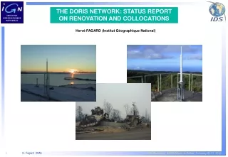
Stations renovations Most stations renovations were motivated by : • The closure or moving of a host agency • Damage to the antenna (e.g. knocked down by a storm) • The need to measure or improve a geodetic connection A station renovation can include some of the following operations : • Antenna change (Alcatel ---> Starec) and/or moving • Monumentation improvement • New geodetic survey • Beacon upgrade (version 1 ---> version 2)
The components of a DORIS station • Beacon: or • Antenna : Alcatel: or Starec: • Backup power supply unit (UPS) • Weather station measuring temperature, pressure and humidity
Distribution of the DORIS equipment + + + 24 stations 19 stations 11 stations
Maintenance statistics • IGN’s maintenance service handles around 130 intervention requests per year (among which 12 beacon exchanges) • Failure causes (model 1.0) : • Power supply : 70 % (should be solved with the 1.1 upgrade) • Oscillator : 15 % • Amplifier : 15 % • Second generation beacons : • 4 failures out of 14 (incl. spares) installed beacons • All failures : amplifier problems • Replacement of 1st generation beacons, until the 3rd generation beacons are available • Average operation rate : 85 % (--> TOPEX coverage > 80 %)
The host agencies National survey agencies (13) Space agencies (11) Telecommunication stations (3) Meteorological stations (3) Other (1) Institutes of oceanography, astronomy or geophysics (12) Other scientific institutes (universities, polar institutes, etc.) (11)
DORIS in the IERS network • DORIS is one of the space geodesy techniques contributing to the realization of the IERS (International Earth Rotation Service) terrestrial reference system • 33 DORIS stations out of 54 are collocated with other techniques: • VLBI (12 sites) • Satellite Laser Ranging (11 sites) • GPS (32 sites) • Half of the collocated stations are in the Southern hemisphere
Collocations with GLOSS tide gauges • 16 DORIS stations are located less than 10 km away from a GLOSS tide gauge • Geodetic connection available at 9 sites (bold names) out of 16
Are the DORIS antennas stable ? The overall antenna stability depends on the stability of: • The mounting structure: • Metal tower (guyed or not) • Steel pole • Metal interface • The monument on which this structure is installed: • Concrete pillar or block (founded or not on the underlying bedrock) • Building • The geological structure on which the monument is located
Antenna location selection: constraints • Beacon inside a building • Clear horizon around the antenna • Antenna cables length: 10 m until 1992, then 15 m
Antenna support: 1st generation (-->1992) • Stability requirement: a few cm (expected DORIS positioning accuracy = 10 cm) • Guyed metal tower: guy-wires not always placed so as to guarantee a long term antenna stability • Alcatel antennas: • Phase center position known to within ± 5 mm • Difficult to survey and center • No accurate verticality adjustment • Catches the wind • Maximum cable length: 10 m • Measured eccentricities after several years:1 to 3 cm
Antenna support: 2nd generation (1993-->) • Stability requirement: 1 cm over 10 years(Achieved DORIS positioning accuracy = 2 to 3 cm) • Starec antennas available: • Phase center position known to within ± 1 mm • Easy to accurately survey and center • Resist high winds • Improved guying and verticality adjustment: • 3 guy-wires @ 120°, whose tension is adjusted to reach a mm level centering • The supporting plate can be leveled so as to adjust the antenna verticality within ± 1 mm • Excellent short term rigidity and stability, but long term stability still dependent on the guy-wires
Antenna support: 3rd generation (recent and future installations) • Stability requirement: better than 1 cm over 10 years (DORIS positioning accuracy approaching 1 cm) • Antenna supports: • Forced centering plate on a concrete monument • Metal mounting structures not needing guying • Monuments: • Prefer ground installation rather than buildings • Concrete pillar founded on bedrock when possible • Buildings: antenna on a load-bearing wall
Evolution prospects: objectives The network’s future evolutions will aim at improving : • The long term stability of the antennas (stations renovation action) • The global coverage (a few more stations to fill in the remaining “holes”) • The equipment’s reliability (deployment of a new generation of beacons)
Improvement of the antennas stability • Stations renovations action under way: • Antenna stability estimation ---> priority list • Several renovations planned in 2000-2001 • Monument stability: • Monument founded on bedrock when possible • Buildings: only low elevation, stable structure • Antenna support: • Interface on concrete monument • Otherwise very rigid tower without guying • Site geodetic survey including footprints • Selection of future sites taking into account their geological stability ?
Third generation beacons • Main new features: • Possible frequency shift, avoiding jamming by nearby stations • Modulated 2 GHz channel • Unambiguous internal International Atomic Time • Can be received even if the time has not been set • Possible remote control through a telephone line or Argos terminal • Planned delivery schedule : • Prototype in July 2000 • 10 units per year from 2001 to 2004
Acknowledgements To all the host agencies : Thank you for your contribution to the success of DORIS