Download
1 / 71
720 likes | 1.06k Views
Digital Telecommunications Technology - EETS8320 Fall 2006. Lecture 2 Analog and Digital Telephone and Wireless Sets (Slides with Notes). Topics of Lecture. What are the major parts (or modules) of a wired landline analog telephone set? What major parts for a digital wireless handset?

E N D
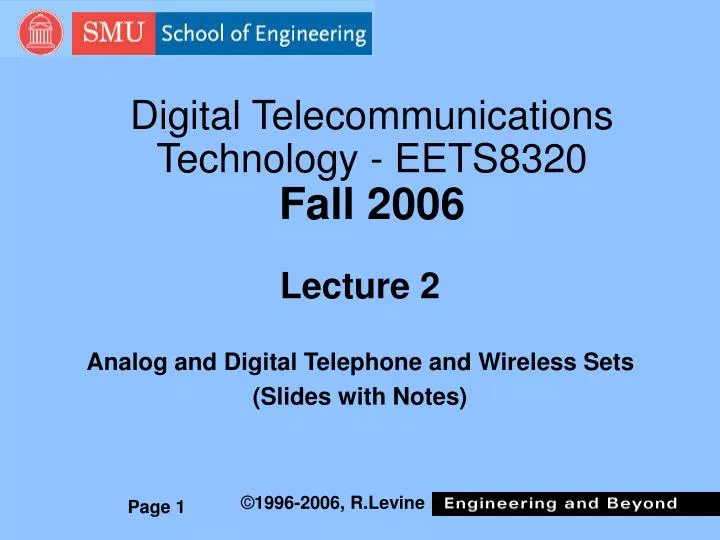
Digital Telecommunications Technology - EETS8320Fall 2006 Lecture 2 Analog and Digital Telephone and Wireless Sets (Slides with Notes)
Topics of Lecture • What are the major parts (or modules) of a wired landline analog telephone set? What major parts for a digital wireless handset? • What functions do these parts perform? • If time permits, we will open and view a wired analog telephone set on camera.
Analog Wired Telephone Set Basic parts/functions of an analog telephone set: • Microphone: converts acoustic waveform (instantaneous incremental air pressure) to electrical audio frequency waveform • Earphone: converts electrical to acoustic waveform • Transmission via wire pair (loop). Directional coupler (hybrid or induction coils) used toaid in separation odf incoming/ outgoing electrical power flow to/from the earphone/microphone respectively. (2-wire/4-wire conversion) • Signaling: • Dialing via rotary current impulse count or via DTMF (touch tone) • alerting via ringer or special sound source • Analog/Digital conversion: • Analog telephone set (digital conversion at central office switch) • A/D conversion in the telephone set for ISDN • Power from central office battery. • Extra Optional Features: Caller ID, stored number dialing, etc.
Digital Wireless (2G) Handset Basic parts/functions of a digital wireless telephone set: • Microphone: converts analog acoustic waveform to analog electrical audio frequency waveform • Earphone: converts analog electrical to acoustic waveform • Analog/Digital conversion: • A/D conversion in the digital cellular handset • Digital signal sent via base-mobile radio link typically comprises 50% digitally coded speech, 50% error protection codes. • Transmission via radio for cellular. Typically separate radio frequencies are used for earphone/ microphone signals (FDD). • Signaling: • Pushbutton dialing via binary coded messages using a separate logical radio channel than the voice. • alerting via special sound source (ring tone generator) activated by message • Power from internal rechargeable battery. • Extra Optional Features: Caller ID, stored number dialing, etc. more so than most landline tel sets.
Direct Acoustic Communication Sound pressure variations at eardrum ultimately cause nerve signals to the brain, perceived as sound. Small variations in air pressure at audio frequencies, produced by the mouth and throat, propagate through the air as an acoustic wave.
Telephonic Communication An ideal telephone system (sometimes called an ortho- telephonic system) reproduces precisely the same acoustic waveform that the listener would hear in a face-to-face conversation. Telephone System A real telephone system only imperfectly reproduces the speech (high frequency components are attenuated, some distortion and delay are introduced as well).
Imperfect Telephone Speech • Telephone speech quality is intentionally sub-optimal • But it does what is needed economically. • Audio Spectrum is intentionally incomplete • Typically 300 Hz to 3500 Hz audio spectrum is adequate for known-language voice communication • Improved audio bandwidth is nice for music, entertainment, but providing it is costly and it adds little to voice intelligibility • Time Delay • Partly due to physical transmission time; partly due to low bit rate coding • Typically 100 to 200 milliseconds is perceptible • Over 200 ms (from geostationary satellite delays) is disturbing to many users • Less disturbing for one-way broadcasting • Small amount of “noise” and distortion is tolerated • Ideally noise is 30 dB “below” (1/1000th) voice power level
Microphone (“Transmitter”) -1 • Carbon microphone is most widely used in analog wire telephone sets • Invented by Thomas Edison; Improved by Emile Berliner • Historically, the Bell “liquid transmitter” was also variable resistance, but impractical due to use of a liquid. • Original Bell commercial telephone used electromagnetic microphone and earphone • Some early telephone sets used two identical devices, some used only one device that the user moved from ear to mouth during the conversation. Electromagnetic “mike” output was weak. • Carbon “mike” is sensitive but low fidelity. • Carbon grain packing is a minor problem.
Microphone (“Transmitter”) -2 • Technical alternatives for modern telephones: • Electro-magnetic microphone • Coil of insulated wire carries varying current due to motion of iron disk (“diaphragm”) near it. Can use either dc coil current or a permanent magnet inside the coil to establish basic magnetic field. • Used in early production (1876) Bell telephones. • Revived (1960s), with transistor amplification correcting the low electrical power level of the signal • Electret microphone • Used in some modern electronic telephone sets, with amplifier • An electret is a permanently electrically polarized solid (analogous to a permanent magnet). Conductive diaphragm near an electrically charged electret surface has varying voltage, responsive to motion caused by air pressure
Some Microphone Types Category Variable Resistance Electro-magnetic Electro-static
Earphone (“Receiver”) • Electromagnetic transducer used almost universally ever since Bell’s original invention. • Magnetically induced force from a current carrying coil of wire acts to flex an iron disk producing sound. • Similar to mechanism of loudspeakers and radio earphones. Loudspeakers typically use a very large moving cone of stiffened paper, mechanically attached to the coil of wire fidtted into a groove near a permanent magnet, to obtain louder sound waves in air • Fidelity is relatively good • Use of same device for earphone and alerting or hands-free loudspeaker may present hazard of ear injury due to loud ringing sound if near the ear when ringing. • Latest gimmick to prevent this is an infra-red beam “proximity detector” in some Nortel handsets. Automatically lowers earphone volume when user’s head is nearby. • A blue grommet where the cord enters the handset on a public telephone indicates “hearing-aid compatible” • Intentional external audio-frequency magnetic field.
Loudspeaker- “Hands Free” • Amplification (sometimes with separate loudspeaker) used for “hands-free” or “speaker-phone” • Continuous amplification may allow audio feedback problems • Hollow, reverberating or echoing sounds due to in-room audio reflections from walls, etc. • Self-oscillation or squealing audio when reflections are too strong • Hands-free sets have some type of echo canceling True echo cancellation (generation of a delayed inverse polarity waveform to cancel the echo) may be accomplished via DSP* or alternatively in the transmission system in the central office switch. • … or automatic audio switching • Mute the loudspeaker when there is local microphone audio • Mute the local microphone when there is audio from distant end. • Local microphone audio can take priority over distant audio. *DSP=Digital Signal Processing
BORSCHT AcronymFunctions in the Tel Set and Switch • Battery: dc electric power • Over-voltage protection: not in the telephone set itself • Ringer: pre-answer alerting in general. May include caller ID feature signal between rings. • Supervision: that aspect of signaling which conveys busy/idle status • Codec: Analog-digital COder/DECoder in a digital telephone system. Not in analog telephone set itself. • Hybrid: directional coupler, 2-wire to 4-wire conversion • Test: modern telephone switches have built-in test capabilities. Simple analog telephone sets have little or no internal test-related equipment.
Landline Central Office Battery • Lead-acid rechargeable batteries in the CO building provide -48 V dc for subscriber loops and also to power almost all the electronic equipment. • In telephone practice the + battery terminal is ultimately connected to the earth/ground. (opposite of vehicle power and most other dc power systems) • This can cause surface corrosion (deposition of copper carbonate or “verdigris”) on the wire but will not “eat away” the copper wire • “Float” charging circuits rectify commercial ac power (110 or 220/208 V ac) and produce dc • Battery is main continuous power source, not just as a back up source. • Backup (if used) comprises Diesel engine, electric power generator (on truck in some cases) and fuel.
Landline Battery Functions • Provides power for loop current supervision • supervision works via cradle switch (“switch hook”) • Provides power for dial signals • Rotary (decadic) dial pulsing • Touch-tone (dual tone multi-frequency – DTMF – oscillator) • Provides power for carbon microphone • Or for amplified electret or electromagnetic microphone. • Allows basic POTS* telephone service in case of municipal electric power failure • Many PBXs have some designated telephone stations which automatically connect to pre-designated outside analog lines via relays actuated when local electric power fails. • Best solution for digital T-1 type PBX trunks or ISDN is overall customer premises telecom power backup systems (UPS, lead-acid gel-cells, etc.) with sufficient reserve power to operate for the anticipated duration of outside power failure *POTS=Plain old Telephone Service
Subscriber Loop Jargon Analog Subscriber Wire Pair • A third wire called Sleeve (C) was used in electro-mechanical switches, but not today in digital switches.
Wireless Battery • Batteries in wireless handsets are mostly secondary (rechargeable) dry cells • After many years of living with batteries designed primarily for flashlights (electric torches) and toys, in the 1990s the wireless market for rechargeable cells got the battery industry to make greatly improved and smaller cells. • Electrode choices of exotic metals such as nickel, cadmium, lithium, etc. produce a light weight repeatably rechargeable (typically up to 100-200 times) battery. • Battery “life” (time between needed recharges) is achieved partly by good system design • Base wireless system broadcasts a sleep-wake time schedule for various ranges of e.g. telephone numbers. Handset can then be automatically internally turned almost completely off (except for a timer and power control device) for up to 90% of the time when not in use, and “awake” only 10% of the time. • All “paging” messages indicative of incoming calls are delayed until the next “awake” time window for that particular group of handsets. • Alerting delay depends on service provider’s schedule, delay is typically 5 to 20 seconds.
Over-voltage Protection • Protect against lightning or “line crossing” with power (mains) wires • Lightning arrestors installed at the point where the outside wire enters the customer or CO premises, limits over-voltage to 300 volts • Most arrestors consist of a simple spark gap with sufficient space between the electrodes so gas between will spark-over (ionize) at ~300 V. Ionization voltage of enclosed gap sealed in dry nitrogen is more uniform and not affected by atmospheric pressure or humidity changes. In an ionized gas many molecules have one ore more electrons removed, thus leaving a net positive electric charged “Ion.” Moving ions and electrons carry electric current across the gap to make the spark. • The insulating (usually ABS plastic) housing of the telephone set is designed to withstand far more than 300 V • Despite all of this protection, telephone operating companies urge subscribers not to make telephone calls during a lightning storm unless absolutely necessary.
Analog Ringer Parameters • Early buzzers or chimes were replaced by low frequency ac ringing signal in late 19th century. • Ringing frequency and voltage used today mimic the early hand-cranked magneto generator, originally used for both subscriber-to-CO and CO-to-subscriber ringing • Ringing ~90 V ac RMS (about 127 V peak for sine wave) • 20 Hz frequency (although other frequencies used for selective ringing on older multi-party lines, etc.) • Occasional problem: Some PBX or key telephone equipment uses square (not sine) waveform with same RMS voltage but lower peak voltage. This waveform will not be detected by some voltage-sensitive electronic ringer devices. • Today many telephone sets use a local audio oscillator triggered by ringing voltage, and a loudspeaker. Local oscillator typically produces a ~1-2 kHz waveform with other higher frequency components as well.
Alerting Audio Requirements • Alerting audio typically contains power at ~1-2 kHz for maximum ear sensitivity • Based on Fletcher-Munson measurements (coming in later lecture) describing relative ear sensitivity at different audio frequencies • Also must contain some higher audio frequencies to permit listener to localize the sound source • Low frequency audio does not allow listener to perceive the direction of the audio source accurately. • Electromechanical metal chime ringer does all of this naturally • A two-tone component “warbling” audio signal is frequently used for non-chime sound. • Ringer current drawn is described by a Ringer Equivalent Number (REN) according to US FCC Rules Part 68. • Example: REN 2.0 ringer draws twice the ringing current vis-à-vis a standard electromechanical ringer.l
Other Ringing Topics • Ringing cadence • North American public telephone systems standardize on a 6 sec cycle: 2 sec ringing and 4 sec silence. • European systems vary widely. Example: UK uses 4 sec cycle with two ring bursts in one sec, then 3 sec silence. • Most public telephone systems do not produce instantaneous ringing burst(s) at the beginning of a call • Delayed ringing bursts are synchronized to the cadence for that portion of the switch’s telephone lines. • Connect-before-ringing could cause “glare”* and false connections • “Bell tap” is a jargon term for any false alerting signal (with an electro-mechanical or an electronic ringer) due to undesired causes: • Transient changes in loop voltage due to decadic dialing, hanging up handset, etc. • Lightning pulses or other “foreign” electrical signals *Glare is a condition due to seizure of both ends of a two-way loop or trunk due to time delay of the test used beforehand by the seizing equipment to determine that loop/trunk is idle vs. busy.
Wireless Ringing/Alerting • When a wireless handset is “on” but idle, its receiver scans the assigned range of radio frequencies, seeking an adequately powerful radio signal having the special signal characteristics that identify a so-called “paging” channel • The exact format of the paging channel is different for GSM, TDMA and CDMA wireless systems, and will be described in a future lecture. • If/when the radio signal strength of that paging channel fades – usually due to the handset moving out of the “cell” -- the handset receiver scans again to find the paging channel of the nearest base antenna cell. • When an incoming call for that handset occurs, a paging message is transmitted (subject to the sleep/wake schedule previously mentioned) on the paging channels in all the cells where the base system “suspects” that the handset may be located. This is in some cases all the cells in the city. • When a handset receives a paging message for itself, it responds with a “here I am” message, and then is commanded to exchange furhter messages, typically on a separate radio channel. One of these is an alerting message, which automatically causes the handset to “ring” (play a pre-recodrded sound or ring tone).
Caller ID • A very popular optional service, which helped to “pay” for Common Channel No. 7 signaling upgrades in the public telephone network. • The originating telephone switch sends a digital call setup message in SS7 format, called the “Initial Address Message” (IAM), containing both the dialed number and the originator’s number. This message is sent via a “common” (shared) call processing data channel, ultimately to the destination switch. If the originator has specified “private” option, a code is also sent indicating not to display the number to ordinary destination subscribers. • If the destination subscriber has subscribed to Caller ID service, and the originator did not forbid it, the caller’s telephone number is transmitted via a modem signal between the first two ringing bursts. A Caller-ID modem* and display at the destination telephone displays the caller number. • If the destination subscriber has also subscribed to caller name ID, the destination switch also obtains the originator’s directory listing name from a separate data base called the Line Information Data Base (LIDB). Each RBOC has its own LIDB. If the originator is outside the area of the destination RBOC, the number will display but the name is typically not available in the destination LIDB. *Actually just the receive part of a modem (a “DEM”). More info later.
Supervision • Supervision is traditionally that part of signaling which conveys busy/idle status • In some systems, the signals for dialed digits etc. are considered distinct from supervision signals. • In new fields of telecommunication, such as wireless, “supervision” is often used to describe all forms of signaling (rather than a subset of all types of signaling), thus leading to jargon confusion when a traditional telephone person discusses technology with a wireless person. • In the analog subscriber loop, dc current flow, controlled by the cradle switch, indicates supervision status • In digital transmission systems, this status may be indicated by digital messages or by means of periodic status bit values (1 vs. 0) that occur in certain digital time division multiplexing bit streams in switching or multiplexing equipment, at predetermined bit locations (like the least significant bit position in one of each 6 consecutive digital frames).
Wireless Supervision • The base system of a wireless call determines a call is still in progress by means of the successful reception of digital messages and digitally coded speech at an adequate power level. Error-protection coding used in the data stream allows evaluation of the amount of erroneous data bits. • An intentional disconnection is the result of pressing the END button on the handset. This produces a repeated and acknowledged disconnect message. • A similar sequence of disconnect messages is used when the other party ends the call. • An unintentional disconnect could occur due to a weak signal or continual excessive data errors for 5 seconds. • This slide describes GSM methods. Other technologies differ in certain ways. GSM service providers can optionally configure their system to automatically reconnect an unintentionally disconnected call, although this requires some processing time.
CODEC (Coder-Decoder) • In most public (analog) telephone installations, the CODEC or analog-digital converter is in the CO equipment (on a “subscriber loop card”). The external loop and customer telephone equipment are all analog • The details of the CODEC will be discussed later in the course • Certain integrated services digital network (ISDN) or proprietary PBX telephone sets have a CODEC in the telephone set, and transmit digital signals to the CO or PBX over the subscriber loop. Digital cell phones have a CODEC in the handset. • The cost of a CODEC was an important factor in the initial introduction of digital end office and PBX switches. Earlier digital multiplexers (channel banks) used a shared CODEC for 24 conversations. • Lower cost due to use of large scale integration allowed the use of a dedicated CODEC microchip for each subscriber loop in an economically feasible design.
CODECs for Wireless • Wireless systems use several different types of CODECs, all presently not waveform coders. • Internal details of various wireless CODECs will be described in a later lecture. • Typical net bit rates for these CODECs is from 6 kb/s to 13 kb/s. Although significantly less than the 64 kb/s used for standard PSTN waveform coding, the quality of most wireless CODECs is very close to the PSTN. • Most parts of a wireless system are designed to allow new CODECs to be easily introduced into service.
Hybrid Coils • “Hybrid coil” is telephone industry jargon for a particular “transformer” type of directional coupler. The version in a telephone set is also historically called an “induction coil” • confusing, since any single coil -- not a multiple winding transformer -- is also called induction coil in general electrical jargon. • Also called 2-wire to 4-wire converter • Permits simultaneous two-way signal power transmission on subscriber loop, • … yet separates microphone and earphone signals at the ends of the 2-wire loop • Uses a multi-winding structure with a “matching circuit” that has approximately the same electrical impedance as the subscriber loop and CO equipment
Background about Transformers*-1 • Prolific American inventor William Stanley made the first transformer in 1886. Transformers have both power and communication uses. • Electric current (moving electrons) produces a magnetic field in space surrounding the current flow. • Intensity and direction of that field mathematically described by a 3-component vector B, measured in volt•sec/meter2 • When an almost-closed piece of conductive wire is placed in that region of space, and the magnetic field changes inside that wire, a voltage appears at the wire ends. • This induced voltage is proportional to the time rate of change of the enclosed magnetic field. For a small area wire “loop” all in one plane, • v = -dB/dt •Area enclosed by wire • This is one of the ways to determine the presence of the magnetic field and to measure its rate of change • The induced voltage can be 2, 3 or more times larger, by wrapping the wire around the same area 2, 3 or more times. • A coil of insulated wire can be both the source and the detector for the magnetic field. Such a coil is usually called an inductor. *Not to be confused with children’s toys (of the 1980s to the present) with parts that can be rearranged to make a robot, a truck (lorry) etc.
Magnetic Induction Arrows represent magnetic B field. Loop area A is about ·(D/2)2, where D is diameter of loop. Loop of wire, with small gap, penetrated by time-varying magnetic field. Field can be caused by current in the loop itself (self-inductance) or due to current in other wires (transformer) or due to a permanent magnet. • We can “stack up” such loops to form a helical coil of wire. Each added “turn” adds another vm volts A voltage Vm will occur here if B is changing with time vm = -dB/dt• A
Background about Transformers-2 g • Electrical inductance measured via a unit called a henry = volt•sec/ampere (abbreviated H) • (Self-) inductance L (in henrys)* of the tightly wound helical insulated coil shown, in terms of its dimensions (meters) and material properties is approximately: • L = µ • n2 •A/g • Where µ is the magnetic permeability of the core material. For air or vacuum µ is 4•p•10-7 henry/meter. If iron is used in the core instead of air, typical µiron is 12000•10-7 henry/meter • n is the total number of turns of wire (n=5 here) • The cross section area of the core A=p•(d/2)2 • g is the length *For most inductors, the unit millihenry (mHy), 1/1000 of a Hy, is used. Incidentally, 4•p= 12.56636 Graphic schematic symbol d
Inductor Electric Properties • Relationship between voltage and current is • v= L•(di/dt) • When the current does not change with time, there is zero voltage. The ideal inductor has effectively zero resistance for dc. Real inductors are typically represented for analysis by a series resistor with an ideal resistance-less inductor. • Following a short voltage pulse, current continues to circulate indefinitely in a closed circuit zero resistance inductor (for example, a “super-conducting” wire inductor) • An appropriate size and duration negative voltage pulse can restore the current to zero, or reverse the current direction if the pulse lasts longer. • A sequence of positive and negative voltage pulses produces an alternating positive and negative current. • When a sine voltage waveform is used, a negative cosine current waveform results. • The sine wave voltage and current are “out of phase” by 90 deg (1/4 cycle). Voltage positive peak occurs ¼ cycle before current peak. • The ratio of the magnitude of the voltage to the magnitude of the current is proportional to the frequency. That is, an inductor “passes” more current (has lower impedance) at lower sine wave frequencies.
Background about Transformers • A transformer comprises two insulated coils (typically multi-turn coils) surrounding the same interior space (typically one coil inside the other) • A time-varying current in one coil will produce a voltage of the same waveform (proportional to time derivative of the current) in both coils • The voltages appearing at the two coils will be proportional to their respective n (number of turns of wire) • Transformer with equal number of turns are typically used to couple electrical non-dc waveforms at same voltage, but to isolate or separate the dc current flow in the primary and secondary winding. • Instantaneous polarity of voltage is fixed by the relative direction of the two windings. A transformer can be used to produce a signal with same voltage waveform on the secondary coil as on the primary, but opposite polarity.
Step-Up or Step-Down • Transformers with unequal number of turns on primary and secondary coil are used to “step up” or “step down” voltage – typically power voltages • Example: in power cords for portable equipment 110 volt ac “primary”coil produces, for example, 6 volts on “secondary” coil for use by low voltage device. Ratio of turns N is 110/6= 18.3 in this example. • Because of change in voltage/current ratio seen via the coupled coils of a transformer, the apparent resistance (in general the “impedance”) of a circuit device is modified per the square of the turns ratio: Schematic transformer symbol i1 Left coil has 2 times the number of turns on right coil. V2=2•v1 and I2=i1/2, So V2/i2=4•R or 40 i2 + - + - v1 v2 R=10
Lowest Frequency for Transformer 1 Power/(N•is)2•R i2 Ideal transformer model i1 Is • Transformers don’t “work” at dc. What is the lowest useful frequency? • In this ideal model of a transformer, used with driving current source Is, and self inductance L, the high frequency power in “load” resistor R is (N•is)2•R. (N is the coils turns ratio n1/n2.) • At dc (zero frequency), the power in resistor R is zero since all current is diverted by the inductor L. At sine wave frequency fc=R/(2pL), resistor power is ½ of its high frequency value. “Half Power Frequency” is convenient to measure. • In telephone transformers, fc is typically 300 Hz by design. This is low enough so speech intelligibility is adequate. + - + - 0.5 + - v1 v2 L R N•v2 N•i1 frequency fc
Implications of Large L value • Inductor value L in previous figure is a representation of the combination of the primary and secondary coil self inductance values • In order to design a transformer that works well at low electrical signal frequencies, its coils must have a large inductance. • Requires many turns of wire, core material with high magnetic permeability (iron or ferrite ceramic, etc.), large area A, etc. • Good power efficiency also requires low wire resistance (not explicitly analyzed here) • Requires thicker (larger wire diameter) wires, use of lower resistance metals (silver, copper, etc.) • These things make the transformer physically larger, heavier and costlier • Every design is a compromise between high efficiency (100 % coupling of electric power from one coil to another) and low size/weight.
Current and Power Flow A B C D + v - - v + • Power flow depends on the polarity of both voltage and current. In the two examples above, current flows from box A to B in the upper wire and returns from B to A in the lower wire. The same directions of current flow exist between boxes C and D. The boxes contain power sources and other circuit elements. • Due to the opposite polarity of the voltage on the wire pairs in the AB vs. the CD case, power flow is toward box B but away from box D. • For your own education, examine two other cases where the voltage is the same as the two cases above, but the current flow is to the left in the top wire and to the right in the lower wire. Power flow Power flow
Transformer Power Flow • Even though a transformer with unequal number of turns on the secondary vs. primary can produce increased voltage, it does not produce increased power • The current flow in the winding with the larger number of turns is inversely proportional to the turns ratio. • Thus the power flow into the primary (product of primary input voltage and current) will ideally be the same as the output power flow from the secondary winding (product of output voltage and current) • Real transformers are slightly less than 100% efficient in transferring power due to the fact that both coils do not always enclose the same total magnetic field area, and due to power loss in the resistance of the wires, certain power loss due to cyclic magnetization and de-magnetization (hysteresis) of the iron or other core material, etc. • A transformer is analogous to a lever: The short end of a lever has high force and small movement, while the long end has low force and large movement. The work (energy) transferred (product of force and distance moved) is the same in at one end of the lever as it is out at the other end!
Transformer Uses in Telephones • Multi-winding transformer in telephone set (“hybrid coil” or “induction coil” together with other components acts as a directional coupler • Directs most of the audio frequency power from the microphone to the CO, rather than to the earphone. • Directs most of the audio frequency power from the CO to the earphone, rather than to the microphone • Simple transformer at CO couples ac speech waveform between subscriber and switching/ transmission equipment, without connecting through the dc loop current • “Hybrid coils” multi-winding transformer at CO separates earphone and microphone audio power into two separate unidirectional signals. • Known as 2-wire to 4-wire conversion. • Many other uses in T-1 transmission lines, ISDN systems, etc. not described here.
Telephone Test Capabilities • Many modern telephone switches have built-in test capabilities • Late at night the subscriber loop is switched over (via relay* contacts on the line card) to a loop tester • Tests are done for on-hook resistance between wires and from each wire to ground • Excessive test current flow (low resistance) indicates problems - usually due to moisture in cables, damaged insulation, etc. • Some trunks can also be tested for idle circuit noise (clicks and pops) • Problems are often caused by moisture in cables. “Wet” cables must be dried or replaced. Drying is often accomplished via infusion of dry nitrogen gas. • Automatic testing anticipates problems, and levels the work load for repair personnel • Built-in test equipment (BITE) is one of the most important features of modern telecom systems * A relay comprises electromechanical switch contact(s) actuated (on/off) by the magnetic field produced by a separate control current.
Manual and Automatic Tests • Craftsperson can dial test numbers • Ringback numbers in the CO switch allow test of the ringer (historic example: 550-xxxx where x’s represent “your own” last 4 digits) • “Quiet line” allows human audible assessment of line noise • Above tests are due to the switching system, not to the analog telephone set. • In PBX and special CENTREX telephone sets, automatic test of each indicator light and button may be performed
Historical Telephone Schematic Earphone (receiver) Microphone (transmitter) _ + Battery • In this simple two-wire circuit, the battery provides dc current to generate a static magnetic field in the earphone. • In the original 1876 Bell installations, the microphone had the same structure as the earphone (magnetic coil and flexible iron diaphragm) so the talk direction through it was reversible (microphone/earphone). • After the 1880s, a permanent magnet was used in the earphone and the more sensitive Edison-Berliner carbon microphone was used. • This simple circuit with carbon microphone is now definitely one-way. • The battery provides current for the carbon microphone.
4-Wire Circuit Simplified physical 4-wire circuit, as used in some military telephone systems _ + _ + Battery Simplified diagram dies not show details of battery feed, dial, ringer, transformer coupling of voice signals, etc.
Historical 2-wire Carbon Mike Circuit Simple, but inefficient and causes excessive “sidetone” in earphones. Desired Destination Earphone. Audio frequency sidetone appears at this earphone. Common battery Installed at Central Office. Switching aspects not shown. Audio input here. _ + Audio frequency power wasted here Audio frequency power from this microphone is “wasted” in the local earphone and the other mike. Simplified diagram dies not show all details of battery feed, ringing, transformer coupling of voice signals, etc.
Hybrid/“Induction” Coil Directional Coupler More efficient, less (not zero) side tone, uses only two wires to CO. Earphone having permanent magnet does not need dc - Secondary winding - Iron core - Split primary winding Line matching circuit Microphone signal current (red arrows) divides, produces canceling effects on secondary winding Two wires to CO switch. Current from distant telephone (green arrows) produces same sense (direction) voltage in secondary, increases audio level. Simplified diagram of “induction coil” in telephone; many actual details set omitted.
Capacitor (“Condenser”) Plate area A sq. meters • Electrical capacitance measured via a unit called a farad = ampere•sec/volt (abbreviated F) • Capacitance C (in farads)* of two metal “plates” separated by an insulating “dielectric” is approximately: • C = e•A/d • Where e is the “dielectric permittivity” of the core material. For air or vacuum e is 8.85•10-12 farad/meter. If plastic is used instead of air, typical eplastic is 50•10-12 farad/meter • A=is the area of each plate • d is the dielectric thickness *For most capacitors, the units microfarad or picofarad (µF or pF) are used d Graphic symbol. Curved line is the outer plate in a “rolled up” capacitor made of flexible metal foil and plastic sheet dielectric.
Capacitor Electric Properties • Relationship between voltage and current is (for ideal non-resistive “plates”) • i = C•(dv/dt) • When the voltage does not change with time, there is zero current. The capacitor “does not pass dc.” • Following a short current pulse, positive charge remains on one plate and equal negative charge remains on the other plate • Electrons have moved from the positive plate to the negative plate. • An appropriate size and duration negative current pulse can restore the electrically neutral status of the plates, or reverse the charge polarity if the pulse last longer. • A sequence of positive and negative current pulses produces an alternating positive and negative voltage. • When a sine voltage waveform is used, a cosine current waveform results. • The voltage and current are “out of phase” by 90 deg (1/4 cycle). Voltage positive peak occurs ¼ cycle after current peak. • The ratio of the magnitude of the current to the magnitude of the voltage is proportional to the frequency. That is, a capacitor “passes” more current (has lower impedance) at higher sine wave frequencies.
Amplifier and A/D converter Telephone Connection with CO Hybrid Coils telephone set and subscriber loop CO part Common battery feed and voice coupling Transmit signal _ Hybrid or “induction coil”and matching network Hybrid and matching network + Receive signal Amplifier and D/A converter 48 V battery Wire loop, up to ~10 km Telephone set (dial, ringer, cradle switch circuits for loop length level compensation not shown) Central office switch equipment. Actual switching is not shown. Positive battery terminal grounded to minimize electrolytic corrosion. Audio frequency voice signals coupled via transformer. Ringing power, loop current detection not shown.
Varistors and their Uses • A varistor is a simple non-linear silicon electrical device used in Type 500, 2500 and related telephone sets for several purposes. • Varistors are made by binding together small grains of impure silicon with a conductive “glue” and fastening on two wires as “terminals,” then coating with plastic. Typically made from “scrap silicon” discarded during the zone refining process. • Unlike a linear electrical resistor, in which current is proportional to voltage (Ohm’s law: v= R•i, where v is voltage, R is constant resistance, and i is current), the current in a varistor increases more than proportionately • An empirical approximate formula for the varistor is i= K•v2, where K is a constant depending on varistor material and size • Sign correction required in this formula since current has same polarity as voltage (current is negative when voltage is negative). Using signum function symbol: i= K•signum (v)•v2. Signum (v) is +1 for positive v, and -1 for negative v.
Varistor Symbol & Graph current • Three varistors are used in a type 500 telephone set: • One parallel with earphone to bypass high peak voltage audio (from power crossing or manual switchboard clicks) • Two in parallel with microphone and matching network, to bypass more microphone audio on short loops (where loop current io is large) so high microphone audio level is not required at the CO. I Schematic symbol io V voltage vo “Incremental” or small signal resistance is re= V/ I. Varies with operating point voltage vo or current io. Larger io gives smaller re.