Download
1 / 24
270 likes | 327 Views
Learn about transmission of information through copper cables, optical fibers, radio waves, or free-space optics. Explore the necessity of switching centers as telephony grows, and understand signaling mechanisms for establishing and maintaining network connections. Discover how conventional telephones operate and how calls are set up and released in a telephone network.

E N D
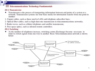
III Telecommunications Technology Fundamentals III-1 Transmission • Transmission is the process of transporting information between end points of a system or a network. Transmission systems use four basic media for information transfer from one point to another: 1. Copper cables, such as those used in LANs and telephone subscriber lines; 2. Optical fiber cables, such as high-data-rate transmission in telecommunications networks; 3. Radio waves, such as cellular telephones and satellite transmission; 4. Free-space optics, such as infrared remote controllers. III-2 Switching • As the number of telephones increase, switching centre (Exchange) become necessary in order to switch signals from one wire to another. Basic Telecommunication network is shown below
III-3 Signaling • Signaling is the mechanism that allows network entities (customer or network switches) to establish, maintain, and terminate sessions in a network. Some examples of signaling on subscriber lines are as follows: • Off-hook condition: The exchange notices that the subscriber has raised the telephone hook (dc loop is connected) and gives a dial tone to the subscriber. • Dial:The subscriber dials digits and they are received by the exchange. • On-hook condition: The exchange notices that the subscriber has finished the call (subscriber loop is disconnected), clears the connection, and stops billing. III-4 Operation of a Conventional Telephone • The ordinary home telephone receives the electrical power that it needs for operation from the local exchange via two copper wires. This subscriber line, which carries speech signals is a twisted pair called a local loop. Figure below shows a simplified illustration of the telephone connection.
III-4-1Signaling to the Exchange from the Telephone • Telephone exchanges supply dc voltage to subscriber loops, and telephone sets use this supplied voltage for operation. But Modern electronic telephones would not necessarily need this if they could take their power from a power socket at home. Setup and Release of a Call • Each telephone has a switch that indicates an on- or off-hook condition. When the hook is raised, the switch is closed and an approximately 50 mA of current starts flowing. This is detected by a relay giving information to the control unit in the exchange • The control unit is an efficient and reliable computer (or a set of computers) in the telephone exchange. It activates signaling circuits, which then receive dialed digits from subscriber A. • The control unit in the telephone exchange controls the switching matrix that connects the speech circuit through to the called subscriber B. Connection is made according to the numbers dialed by subscriber A. • When the call is being routed to subscriber B, the telephone exchange supplies to the subscriber loop a ringing voltage and the bell of subscriber B’s telephone starts ringing. The ringing voltage is often about 70V ac with a 25-Hz frequency • The ringing voltage is switched off immediately when an off-hook condition 24 Introduction to Telecommunications Network Engineering is detected on the loop of subscriber B, and then an end-to-end speech circuit is connected and the conversation may start.
Figure below shows the signaling phases on a subscriber loop. When the exchange detects the off-hook condition of a subscriber loop, it informs us with a dial tone that we hear when we raise the hook that it is ready to receive digits. After dialing it keeps us informed about whether the circuit establishment is successful by sending us a ringing tone when the telephone at the other end rings. • When subscriber B answers, the exchange switches off both the ringing signal and the ringing tone and connects the circuit. • At the end of the conversation, an on-hook condition is detected by the exchange and the speech circuit is released.
Types of Dialing • Rotary Dialing: The telephone set has a switch that is open in the on-hook condition and closed when the hook is off. It use the principle of local loop connection/disconnection in order to transmit digits, We call this principle rotary or pulse dialing • In rotary dialing a local loop is closed and opened according to the dialed digits, and the number of current pulses is detected by the exchange • When a digit is to be dialed, the dialing plate with finger holes is rotated clockwise to the end and released. While homing, the switch is breaking the line current periodically and the number of these periods indicates the dialed digit. • For example, digit 1 has one period, 2 has two periods, and 0 has 10 periods or cycles. Mechanics make the homing speed approximately constant and each period is about 100 ms long with a 60-ms break, see figure below
Tone Dialing: Modern telephones usually have 12 push buttons for dialing, each generating a tone with two frequencies. One of the frequencies is from the upper frequency band and the other from the lower band. All frequencies are inside the voice frequency band (300–3,400 Hz) and can thus be transmitted through the network from end to end, when the speech connection is established. • This signaling principle is known as dual-tone multi frequency (DTMF) signaling. • Tones are detected at the subscriber All digital local exchanges have a capability to use either pulse or tone dialing on a subscriber loop. The subscriber is able to select with a switch on his telephone which type of dialing is to be used. • Tone dialing should always be selected if the local exchange is a modern digital one. • Advantages of tone dialing are as follows: • It is quicker and dialing of all digits takes the same time. • Fewer dialing errors result. • End-to-end signaling is possible. • Additional push buttons are available (*, #, A, B, C, D) for activation of supplementary services.
Local Loop and 2W/4W Circuits: Any use of telephone channels involves two unidirectional paths, one for transmission and one for reception. The local loop, which connects a telephone to a local exchange is a two-wire (2W) circuit that carries the signals in both transmission directions see figure below. Even ISDN and asymmetrical digital subscriber lines(ADSLs) use this same 2W local loop. • Longer connections attenuate the speech signal and amplifiers are needed on the line. In two-wire circuits, amplification of a signal may cause oscillation or ringing . • The operating principle of electronics in the network is unidirectional and inside the network we use two wires for each direction, or four-wire (4W) connections. Four-wire connections are also much easier to maintain than 2W connections because transmission directions are independent from each other and oscillation is avoided.
To connect a 2W local loop to a 4W network a circuit called a 2W/4W hybrid is needed • Figure below shows the 2W/4W hybrid in a subscriber interface of the telephone exchange. • The 2W/4W hybrid performs the following operations: • Separates the transmitting and receiving signals. • Matches the impedance of the 2W local loop to the network circuit. • Provides a loss to signals arriving on the receiving path, preventing them from entering the transmitting path, which would cause echo.
Figure below shows an example of a segment of a network in which two- and four-wire circuits are traditionally used.
Telephone Numbering • An international telephone connection from any telephone to any other telephone is made possible by unique identification of each subscriber socket in the world • In mobile telephone networks, each telephone set (or subscriber card) has a unique identification number. • The numbering is hierarchical, and it has an internationally standardized country code at the highest level • The structure of the telephone number hierarchy is shown below. • Note: In the case of cellular service, the trunk code is used to identify the home network of the subscriber instead of the location
Switching and Signaling • To build the requested connection from one subscriber to another, the network has switching equipment that selects the required connection. • These switching systems are called exchanges. The subscriber identifies the required connection with signaling information (dialing) that is transmitted over the subscriber line. • In the network, signaling is needed to transmit the control information of a specific call and circuits from one exchange to another. • Telephone Exchange • The main task of the telephone or ISDN exchange is to build up a physical connection between subscriber A, the one who initiates the call, and subscriber B according to signaling information dialed by subscriber A. • In the past, the switching matrix was electromechanical and controlled directly by pulses from a telephone. • Currently, the common control unit is an efficient and reliable computer or a multiprocessor system, including large amounts of real-time software. This kind of exchange is called a stored program control (SPC) exchange as shown in the figure below.
Signaling • The control unit of the local exchange receives the subscriber signaling, such as dialed digits, from the subscriber line and makes consequent actions according to its program • Usually the call is routed via many exchanges and the signaling information needs to be transmitted from one exchange to another. • This can be done via channel associated signaling (CAS) or common channel signaling (CCS) methods . • common channel signaling (CCS) method is the modern interexchange signaling system. It is based on the principles of computer communications • Signaling contain, for example, information about the connection to which the message belongs, the address of the destination exchange, dialed digits, and information about whether subscriber B has answered. • In Figure below we see an example in which an ordinary fixed network subscriber, subscriber A, calls subscriber B when CCS is used between exchanges in the network.
The dialed digits are transmitted from subscriber A to the local exchange. When a set of digits is received by exchange A, it analyzes the dialed digits to determine to which direction it should route the call. From this information it looks up an address of the exchange to which it should send the signaling message for call connection. • Then the exchange builds a data packet that contains the address of exchange B. This signaling message, called the initial address message (IAM), is then sent to exchange B. The remaining digits that did not fit into the IAM are transmitted in one or more subsequent address messages (SAMs). • When all the digits that identify subscriber B are received by exchange B, it acknowledges this with an address complete message (ACM), to confirm that all digits have been successfully received. This message also contains information about whether the call is to be charged or not and if the subscriber is free or not. • Exchange B transmits the ringing tone to subscriber A and the ringing signal to subscriber B, and telephone B rings. When subscriber B lifts the handset, an answer signal charge (ANC) is sent in order to activate charging. Exchange B switches off the ringing signal and ringing tone.
Then both exchanges connect the speech channel through so the conversation can start. • When subscriber B hangs up, exchange B detects an on-hook condition and sends a CBK to exchange A. • Exchange A responses with CLF signal. All exchanges on the line transmit the CLF message to the next one, and each receiving exchange acknowledges it with a release guard (RLG) signal. This is to ensures that both exchanges have cleared the circuit to make it available for a new call.
Switching Hierarchy • As telephone density grew and subscribers desired longer distance connections, it became necessary to interconnect the individual service areas with trunks between the central offices. • The actual implementation of the hierarchy and the number and names of switching levels differ from country to country. Figure below shows an example of a possible network hierarchy • The hierarchical structure of the network helps operators manage the network and it makes the basic principle of telephone call routing straightforward; the call is routed up in the hierarchy by each exchange if the destination subscriber is not located below this exchange.
Telephone Call Routing • Calls that are carried by the network are routed according to a plan, a set of rules. The routing plan includes the numbering plan and network configuration. • The global rules for the highest-level numbering, country codes, and overall numbering (maximum length and so on) are given by ITU-T. (International Telecommunication Union- Standardization Sector) • The national telecommunications authority coordinates the national numbering plan. It defines, for example, trunk or area codes and operator prefixes used inside the country. It also defines nationwide service numbers (e.g., emergency numbers) • From the received signaling information (dialed digits), a switching system must be able to interpret the address information, determine the route to or toward the destination, and manipulate the codes in order to advance the call properly.
The basic routing principle is hierarchical: If the destination does not belong to the subscribers of the switch or of the switches under it, the call is routed upward; otherwise, it is routed to the port toward that destination • In the example of Figure below, a Finnish subscriber makes a call to Stockholm, Sweden, and dials the international prefix “00,” country code “46” for Sweden, area code “(0)8” (leaves out zero) for Stockholm, and subscriber number “xxxxx.” The international prefix is actually all that the lower-level exchanges in Finland need to know. • When exchanges in the switching hierarchy detect it, they route this call up toward the international exchange. The international exchange then analyzes the country code and selects an outgoing route to Sweden. • Another example in Figure below illustrates routing of a long-distance call from a subscriber in another region. A subscriber in another region dialed “09 13115” for a long-distance call to Helsinki. The first digit “0” tells the exchanges that this is a long-distance call and is to be routed to the regional exchange. The regional center is connected to other regional centers and then routes this call, with the help of other regional centers, to Helsinki according to the next digit, “9.” The regional center of Helsinki analyzes the next two numbers, “13,” and selects the route down to the primary center where these subscribers are located. (Operator has defined in his numbering plan that the subscriber numbers 2xxxx and 1xxxx are placed on the left-hand branch from the regional center.) • The primary center then checks the following numbers, “131,” and notices that this is not “my subscriber” but the destination subscriber is located “below me” and routes the call to the corresponding lower-level exchange, in this example, the local exchange. • The local exchange selects the subscriber loop of the telephone number 13115 and connects a ringing signal to the subscriber.
Local-Access Network • The local-access network provides the connection between the customer’s telephone and the local exchange. • Ordinary telephone and ISDN subscribers use two wires, a pair, as a subscriber loop, but for business customers a higher capacity optical fiber or microwave radio link may be required. • Many different technologies are used in a local-access network to connect subscribers to the public telecommunications network. • Most subscriber connections use twisted pairs of copper wires. Subscriber cables contain many pairs that are shielded with common aluminum foil and plastic shield. • In urban areas cables are dug into the ground and may be very large, having hundreds of pairs. Distribution points that are installed in outdoor or indoor cabinets are needed to divide large cables into smaller ones and distribute subscriber pairs to houses as shown in Figure below (Local Access Network). • In suburban or country areas, overhead cables are often a more economical solution than underground cables.
An optical connection is used when a high transmission capacity (more than 2 Mbps) or very good transmission quality is required. • A microwave radio relay is often a more economical solution than optical fiber when there is a need to increase data capacity beyond the capacity of an existing cable network. Installation of optical or copper cables takes more time because permissions from landowners and city authorities are required. • One technology for implementation of ordinary subscriber loops for fixed telephone service is known as wireless local loop (WLL) which use radio waves. • When cable network capacity for subscriber connections needs to be increased, it may be more economical to install concentrators, remote subscriber units, or subscriber multiplexers so as to utilize existing cables more efficiently.
Local Exchange • Local or subscriber loops connect subscribers to local exchanges, which are the lowest-level exchanges in the switching hierarchy. These are the main tasks of the digital local exchange: • • Detect off-hook condition, analyze the dialed number, and determine if a route is available. • Connect the subscriber to a trunk exchange for longer distance calls. • Connect the subscriber to another in the same local area. • Determine if the called subscriber is free and connect ringing signal to her. • Provide metering and collect charging data for its own subscribers. • Convert 2W local access to 4W circuit of the network. • Convert analog speech into a digital signal (PCM). • The size of local exchanges varies from hundreds of subscribers up to tens of thousand subscribers or even more. A small local exchange is sometimes known as a remote switching unit (RSU) and it performs the switching and concentration functions just as all local exchanges do.
Trunk Network • Figure below shows a simplified structure for a network where higher levels than local exchanges are shown as a single level of trunk exchanges. • The local exchanges are connected to these trunk exchanges, which are linked to provide a network of connections from any customer to any other subscriber in the country. • High-capacity transmission paths, usually optical line systems, with capacities up to 10 Gbps, interconnect trunk exchanges. Note that a transport network has alternative routes. If one of these transmission systems fails, switches are able to route new calls via other transmission systems and trunk exchanges to bypass the failed system (see the figure). • The trunk exchanges are usually located in major cities. They are digital and use the international common channel signaling standard SS7 to exchange routing and other signaling information between exchanges.
International Network • Each country has at least one international switching center to which trunk exchanges are connected, as shown in Figure below. • Via this highest switching hierarchy level, international calls are connected from one country to another and any subscriber is able to access any of the other more than 2 billion subscribers around the world. • High-capacity optical systems interconnect international exchanges or switching centers of national networks. Submarine cables (coaxial cable or optical cable systems), microwave radio systems, and satellites connect continental networks to make up the worldwide telecommunications network. • Modern optical submarine systems have a capacity of several hundred thousand speech channels
Traffic Engineering • Traffic engineering is a key issue for telecommunications network operators trying to keep customers (subscribers) happy while minimizing network investments. • The capacity of the network (e.g., number of channels between exchanges, exchange sizes, number of radio channels in a cellular network) should be increased where the bottlenecks of the network are found. An important capacity planning method is based on theoretical analyses of capacity demand. Grade of Service • How happy subscribers are depends on the grade of service (GoS, availability or quality of the service) they receive. The GoS depends on the network capacity that should meet the service demand of the customers. • In Figure below, blocking occurs if more than n subscribers make external calls at a time. For the probability of unsuccessful calls, operators define the target value, the highest probability of an unsuccessful call that they assume to be acceptable for their customers. • The smaller this probability is, the more capacity they have to build into the network. • Another factor we could use to define GoS is how long the subscriber has to wait until the service becomes available. We could design the network to keep customers in a queue until, for example, a transmission channel becomes free
Busy Hour • Network capacity planning is based on the so-called busy hour traffic intensity. • Busy hour is an hour in the year when the average traffic intensity gets the highest value. • The basic goal is to find a minimum capacity that gives the defined grade of service Traffic Intensity and the Erlang The measure of traffic intensity for circuit-switched connections is called the erlang • The erlang unit is defined as (1) a unit of telephone traffic specifying the percentage of average use of a line or circuit (one channel) or (2) the ratio of time during which a circuit is occupied and the time for which the circuit is available to be occupied. • Traffic that occupies a circuit for 1 hour during a busy hour is equal to 1 erlang. • Consider these examples: • If the traffic intensity of a subscriber line is 1 erlang, the line is occupied for 60 minutes in an hour. • If a subscriber line is in use 6 minutes out of an hour (on average), the traffic intensity is 6 minutes/60 minutes or 100 mErl. • The maximum traffic intensity of a 2-Mbps (30 PCM channels) line system is 30 erlangs, that is, all channels are in use 60 minutes during the busy hour. • The typical average busy-hour traffic volume generated by one subscriber is in the range of 10 to 200 mErl.