Download
1 / 49
490 likes | 641 Views
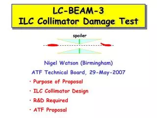
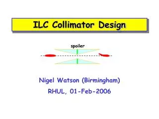
spoiler. ILC Collimator Design. Nigel Watson (Birmingham) RHUL, 01-Feb-2006. Outline. Motivation ILC Physics goals Luminosity Introduction Spoiler Wakefield + Mechanical Design project Wakefields Spoiler Damage Summary NB: Preliminary results, work of many people, credits throughout.

E N D
spoiler ILC Collimator Design Nigel Watson (Birmingham) RHUL, 01-Feb-2006
Outline • Motivation • ILC Physics goals • Luminosity • Introduction • Spoiler Wakefield + Mechanical Design project • Wakefields • Spoiler Damage • Summary NB: Preliminary results, work of many people, credits throughout ILC Collimator Design / Nigel Watson
σ (fb) all quarks (excl. top) 106 tt W+W- 103 Zh 1 HA 0 200 400 600 800 1000 √s (GeV) Linear Collider Physics • Interesting physics requires high energies • Cross-sections verysmall • High luminosity essential • New challenge: beamstrahlung New: see LHC-LC Study Group, Georg Weiglein et al., hep-ph/0410364 (485 pages) ILC Collimator Design / Nigel Watson
200 No. of events / 15 GeV 100 0 100 120 140 160 1 recoil mass (GeV) 10-1 H0 BRanching fraction 10-2 mass/GeV 100 120 140 10-3 Higgs Measurements • Mass: recoil spectrum of μ+μ- Z μ+ μ- • BR: use good pid/vtx • Uniquely predicted • Only possible at ILC ILC Collimator Design / Nigel Watson
Higgs • Higgs (or equivalent) will be discovered at LHC • Detailed properties • Mass, coupling, JPC, BR all measured independent of model • Only accessible with ILC • H self-coupling, implicit for known mH and <f>, test consistency ILC Collimator Design / Nigel Watson
pre-accelerator few GeV source Beam Delivery System KeV extraction damping 250-500 GeV ring & dump few GeV final focus few GeV IP bunch main linac compressor collimation [N.Walker] The ‘Generic’ Linear Collider • All sub-systems define state-of-art in accelerator design • UK concentrating on BDS (~ technology indep.) • Strong world-wide support for this (GDE, etc.) ILC Collimator Design / Nigel Watson
Introduction • Success of ILC requires • High (integrated) luminosity • Acceptable backgrounds • Machine protection (~10MW/beam) • Detectors must be able to turn on and use recorded data • High luminosity • Minimise emittance growth, DR IP • Control relative beam-beam motion at IP • High beam currents ILC Collimator Design / Nigel Watson
[c/o L.Keller, DL seminar, Nov. 2005] SLAC Damage Test - 1971 Beam scraping the edge of a 60 cm long copper block 60 cm 500 kW Beam Beam diameter ~ 2000 µ It took about 1.5 sec to melt thru the 60 cm block, but for this relatively large beam, the front few radiation lengths remain intact. ILC Collimator Design / Nigel Watson
Spoiler/Absorber • Thin (<1X0) spoilers • Reducebeamenergy density, multiple Coulomb scattering, dE/dx • Low z bulk, but require durable, low resistivity surface • Thick (20-30X0) absorbers, in spoiler shadow spoiler absorber SLC, 20mm Au coating on Ti [Decker et al, Linac’96] 1mm ILC Collimator Design / Nigel Watson
Collimator Wakefields • Mechanical collimators close to beam • Conservative assumption (SLC) • Design system to remove ~ 10-3 of beam • Beam excites wake potential in material, acts back on (tail of) bunch: • Transverse loss (“kick”) factor, y’=Ky (near axis) • Position jitter angle jitter • Energy jitter betatron motion (collim. in finite dispersion region) • Single bunch emittance dilution • Collim at betatron phase of Final Focus Doublet most critical • FFD, vertical beam size from sy~ mm to nm • Contribute to position jitter of beam at IP – lowers luminosity! ILC Collimator Design / Nigel Watson
Collimator Wakefields • WF in vertical plane important even in error free machine • Collim at betatron phase of FD most criticaL • Contribute to position jitter of beam at IP • Factorise into geometric and resistive effects • Very difficult to calculate analytically - possible for simple, symmetric configurations • Difficult to model, esp. for short bunches, shallow tapers, in reasonable time • More measurements essential to improve modelling/theory ILC Collimator Design / Nigel Watson
Data • Improvements to theory (Stupakov et al) • Very difficult to calculate analytically - possible for simple, symmetric configurations • Resistive wakes (tapered rectangular) • Kicks • Geometric wakes (tapered, rectangular) collimators • Inductive (shallow tapers) • Intermediate regime • Diffractive (steep tapers) • 3 runs with dedicated facility at SLAC, study geometric and resistive wakes, 2000-2004 • Analytic calculations used in TRC, assuming • is = Cu • No tail folding • Near-axis wakes (linear, dipole region) Behaviour on ½ gap, r, predicted ~ 1/r2 – 1/r3/2 ILC Collimator Design / Nigel Watson
X~5 X~25 Concept of Experiment BPM BPM BPM BPM Vertical mover • Wakefields measured in running machines: move beam towards fixed collimators • Problem • Beam movement oscillations • Hard to separate wakefield effect • Solution • Beam fixed, move collimators around beam • Measure deflection from wakefields vs. beam-collimator separation • Many ideas for collimator design to test! ILC Collimator Design / Nigel Watson
X~5 X~25 Concept of Experiment BPM BPM BPM BPM Vertical mover • Wakefields measured in running machines: move beam towards fixed collimators • Problem • Beam movement oscillations • Hard to separate wakefield effect • Solution • Beam fixed, move collimators around beam • Measure deflection from wakefields vs. beam-collimator separation • Many ideas for collimator design to test! ILC Collimator Design / Nigel Watson
Wakefield Box 1500mm Ebeam=1.19GeV Sector 2, sz ~ 500mm sy ~ 100mm Magnet mover, y range = 1.4mm, precision = 1mm ILC Collimator Design / Nigel Watson
e.g. Resistive Wake Study • Initial study was of geometric wake – same material, different geometry • Second run: Cu vs. Graphite (same shape) • Reasonable agreement with resistive wake theory kick angle gap position [From Onoprienko, Seidel, Tenenbaum, EPAC’02] ILC Collimator Design / Nigel Watson
Third Set of Collimators [Tenenbaum+Onoprienko, EPAC’04] • Continued study of resistive wakes, compare Cu vs. Ti • Resistive theory underestimates (high s) Cu data • (3.87-1.4)/(2.3-1.4) i.e ~x2.8+/- 0.1 beam ILC Collimator Design / Nigel Watson
Wakefield Reduction Methods • Optimisation of collimator form – need reliable/validated predictions • Ideal case - very long taper, circular • Realistic – available longitudinal space, adjustable (rectangular) • 2-step tapers • More complex shapes, non-linear tapers? • Tail folding – but should be verified experimentally before relying upon this to solve all problems • Increase vertex radius at IP? • “to some extent vxd radius is a free parameter…” • Discussion ILC Collimator Design / Nigel Watson
Improved Predictions • Theoretical/Modelling • Zagorodnov, Weiland: ECHO • Uniformly Stable Conformal approach – very close to stable absolute error, ~ % • ~ indep. of collim. length • Even in region close to origin • Applicable for non-linear, near-wall wakes. • Essential improvements, permit more reliable optimisation [Yokoya formula] transverse wake ILC Collimator Design / Nigel Watson
[From Zagorodnov and Weiland, TESLA Collab, Jan 2004] ILC Collimator Design / Nigel Watson
Planning • Unique facility, already one good collab.(Mike Seidel) with SLAC on C collimators • Progress slow – need two interventions and lots of technical experts to install new collimators, plus operation time ~1.5years between runs • Studying basic physics effects which are indep. of (eventually cold) technology choice • Improved theory/methods also applicable to future light sources (sz<<ILC sz), important to labs. ILC Collimator Design / Nigel Watson
Spoiler Wakefield+Mechanical Design Design / optimisation of spoiler jaws (geometry and materials) for wakefield and beam damage performance • Development of improved EM modelling methods • Benchmarking of wakefield calculations against experiments • RF bench tests (training/code comparisons) • SLAC ESA beam test / data analysis • Tracking simulations with best models of wakefields • Simulations of beam damage to spoilers • Material studies using beam test Project web: http://hepunx.rl.ac.uk/swmd/ ILC Collimator Design / Nigel Watson
People • UK project integrated with EUROTeV “Spoiler Wakefield and Mechanical Design” task • Project web: http://hepunx.rl.ac.uk/swmd/ • Birmingham: NKW (+D.Adey, M.Stockton) • CCLRC: C.Beard,G.Ellwood,J.Greenhalgh,J.O'Dell,L.Fernandez • CERN: F.Zimmermann,D.Schulte [EUROTeV] • DESY: I.Zagorodnov [EUROTeV] • Lancaster: D.Burton,N.Shales,J.Smith,A.Sopczak,R.Tucker • Manchester: R.Barlow,A.Bungau,G.Kurevlev,A.Mercer+R.Jones • TEMF, Darmstadt: M.Kärkkäinen,W.Müller,T.Weiland [EUROTeV] • For ESA tests, working closely with • F.Jackson (CCLRC)on optics for wakefield and beam damage studies • M.Woods, P.Tenenbaum, R.Arnold, +…(SLAC)for all aspects • For evolving damage studies, L.Keller, M.Ross, M.Seidel, DESY/SLAC/… ILC Collimator Design / Nigel Watson
GdfidL MAFIA 1mm Long. wake (V/pC) Collimator length>>bunch length Large computational problem S (m) 1m Wakefield Modelling • Increased emphasis on simulations • Development of ECHO-3D [TEMF, Darmstadt] • Baseline simulations: MAFIA (C.Beard), GdfidL (J.Smith) • RF bench tests, not directly applicable for ILC bunch length • Training and code benchmarking – extrapolation to short bunches t.b.c. Collab. with A.Liapine (UCL) for GdfidL Sensitive to mesh definitions [Contacts with Bruns, Ng, Corlett] ILC Collimator Design / Nigel Watson
RF Bench Tests ~1.7m • From DL SRS tests (sz~6mm) • Consider vertical plane operation to avoid sag • Critical issue: • Pulse speed • Time ~ LC bunch sz • ~1 ps • Survey, fastest available “off the shelf” pulse generator for TDR ~ 10ps (Tek. 80E04 module+PSPL module+ TDS8200 scope) • Use for training/benchmarking in general of codes [From Hill&Pugh, EPAC’94] ILC Collimator Design / Nigel Watson
Testbench (ASTeC/CI) Impedance Rig [Carl Beard] ILC Collimator Design / Nigel Watson
Test Vessels Hardware Recovery Impedance Rig 2 Matching parts [Carl Beard] Launch cone ILC Collimator Design / Nigel Watson
Initial (old) setup • Decided bench tests not critical prior to ESA beam • Useful for benchmarking code • In preparation at DL this week (Beard/Jones/Smith/Fernandez) • Perhaps production testing • Validity of extrapolation would have to be demonstrated Tektronics 7854 TDR ‘scope 6 GHz NA, S-parameter test set ILC Collimator Design / Nigel Watson
Collimator Wakefield Beam Test (T-480) • Wakefield beam tests at ESA • SLAC Proposal T-480 (Tenenbaum, Watson et al), 4/2005 Many people involved directly, see proposal • Part of evolving programme of ILC tests at ESA • Purpose • Commision/validate CollWake Expt. at ESA • Additional study of resistive wakes in Cu • First study of 2-step tapers • Development of ECHO-3D code (TEMF) for shallow tapers/short bunches • Schedule • Commissioning, 4-9 Jan. 2006, 4 (old) collimators • Physics, 24-Apr – 8-May 2006, 8 new collimators (CCLRC) • Status • Beamline prep., DAQ, BPM set up ongoing • 5 sets of collimator jaws designed/fabricated at RAL (O’Dell, Greenhalgh) at SLAC, remaining 3 sets will ship <end Feb. ‘06 • Related activity • Implementation of validated/realistic 3D wakefunctions in Merlin • Collimator damage studies considered for ESA/TTF ILC Collimator Design / Nigel Watson
ESA beamline layout (plan) Wakefield box Beam • Measure kick factor using incoming/outgoing beam trajectory, scanning collimator gap through beam • Stage 1, 5 rf cavity BPMs, 1 stripline BPM, 2 wire scanners • Wakefield box, proposal for 2 sets of four pairs of spoiler jaws • Each set mounted in separate “sandwich” to swap into WF box • (Relatively) rapid change over, in situ – to be attempted! • Commissioning run, Jan 4-9, 2006 • Physics run, 24-Apr – 8-May, 2006 ILC Collimator Design / Nigel Watson
Wakefield box 1500mm Ebeam=28.5GeV ESA sz ~ 300mm – ILC nominal sy ~ 100mm (Frank/Deepa design) Magnet mover, y range = 1.4mm, precision = 1mm ILC Collimator Design / Nigel Watson
Optical design • Optical design of A-line for WF expt., WP1.1 (F.Jackson/D.Angal-Kalinin) sy~100mm and flat in vicinity of WF box ILC Collimator Design / Nigel Watson
Wakefield Box Relocation ILC Collimator Design / Nigel Watson
Successful commisioning run 4-9 Jan. 2006 Wakefield box sy = 117 mm Beamline preparation at SLAC - Ray Arnold Wire scanner measurement of vertical spotsize. ESA Test Beam for T-480 ILC Collimator Design / Nigel Watson
ILC Beam Tests in End Station A SLAC EPAC Meeting January 24, 2006 Collimator design, wakefields (T-480) BPM energy spectrometer (T-474) Synch Stripe energy spectrometer (T-475) IP BPMs/kickers—background studies EMI (electro-magnetic interference) http://www-project.slac.stanford.edu/ilc/testfac/ESA/esa.html PAC05 paper/poster: SLAC-PUB-11180, e-Print Archive: physics/0505171 M.Woods, SLAC ILC Collimator Design / Nigel Watson
Energy profile with SLM digitized (saturates at peak) 1.2% dE/E January 2006 Commissioning Run Successful! 117-micron vertical spot Energy profile with SLM digitized (saturates at peak) 1.2% dE/E Wire scanner measurement of vertical spotsize. Nominal setup had low energy tail. Optimizing Linac injection phase and compressor voltage for short bunches eliminates low energy tail and gives high energy tail. M.Woods, SLAC ILC Collimator Design / Nigel Watson
38 mm h=38 mm L=1000 mm a r=1/2 gap As per last set in Sector 2, commissioning Extend last set, smaller r, resistive WF in Cu 7mm cf. same r, tapered ILC Collimator Design / Nigel Watson
38 mm h=38 mm 7 mm Cf. slot 4, set A, smaller r Cf. slot 2, same r 211mm 31mm Cf. slot 4, set A,and slot 2 133mm Cf. slot 3, and same step in/out earlier data ILC Collimator Design / Nigel Watson
[c/o L.Keller, DL seminar, Nov. 2005] SLAC Damage Test - 1971 Beam scraping the edge of a 60 cm long copper block 60 cm 500 kW Beam Beam diameter ~ 2000 µ It took about 1.5 sec to melt thru the 60 cm block, but for this relatively large beam, the front few radiation lengths remain intact. ILC Collimator Design / Nigel Watson
NLC Exotic Designs (SLAC) [J.Frisch, CollTF 2002] ILC Collimator Design / Nigel Watson
More Exotic [J.Frisch, CollTF 2002] ILC Collimator Design / Nigel Watson
Examples of Direct Hits on Titanium Alloy Spoilers Maximum ΔT/ 2x10¹⁰ bunch at the Hit Location, ºC/bunch Collimator simulated rectangular, no tapers Notes: • Ti–6Al–4V alloy – fracture 770 ºC, melt 1800 ºC • Copper – melt 1080 ºC [c/o L.Keller, DL seminar, Nov. 2005] ILC Collimator Design / Nigel Watson
Damage Studies • Initial ANSYS studies to check steady state heating (Ellwood, Kurevlev) • Next steps, real energy deposition profile (Fluka/Geant4) • Discussions started with Lew Keller, Nov. ’05 • Agreement EGS/FLUKA/G4 • Temperature rises critically dependent on cell sizes considered! • Study transient effects, fracture, etc. • Use CCLRC (AMG/EID) expertise • Beam tests to be designed following simulations • Quantify “damage” - hard • Consider using new ESA collimators – assess impact on measured wakefields [G.Ellwood, RAL] ILC Collimator Design / Nigel Watson
Beam Collimator (modelled with GEANT4) Dimensions: x = 38 mm y = 17 mm z = 21.4 mm Z = 122.64 mm Material:Ti alloy (Ti-6Al-4V) melting temperature: 1649 C Beam profile:σx=111µm σy =9µm (ellipsoid); E = 250 GeV (104electrons/bunch); Energy cutoff:e- kinetic energy cutoff = 2.0 MeV -> 2.9 mm range in Ti alloy e+ kinetic energy cutoff = 2.0 MeV -> 3.1 mm range in Ti alloy γenergy cutoff = 100.4 KeV-> 6.18 cm attenuation length in Ti alloy [A.Bungau, Manchester] ILC Collimator Design / Nigel Watson
Spoilers considered… [L.Fernandez, ASTeC] 250, 500 GeV e- 2 mm, 10mm Ti/C 0.6 Xo of Ti alloy leading taper (gold), graphite (blue), 1 mm thick layer of Ti alloy 0.3 Xo of Ti alloy each side, central graphite part (blue). ILC Collimator Design / Nigel Watson
beam Ti C Preliminary 2 mm deep from top Ti alloy and graphite spoiler Temperature data in the left only valid the Ti-alloy material. Top increase of temp. in the graphite ~400 K. Dash box: graphite region. 540 K 405 K 400 K 270 K ∆Tmax = 575 K per a bunch of 2E10 e- at 500 GeV σx = 79.5 µm, σy= 6.36 µm [L.Fernandez, ASTeC] ILC Collimator Design / Nigel Watson
beam Single ILC bunch Realistic energy depostion in spoiler from FLUKA Consistent results from G4/EGS Transient mechanical stress, temperature rise from ANSYS ILC Collimator Design / Nigel Watson
beam 2 ILC bunches [Ellwood/RAL] • ANSYS for transient mechanical stress, temperature rise • Peak stress from bunch 1 ~ arrival time of bunch 2 • Time structure important for tests • Realistic spoiler energy depostion from FLUKA • Consistent results from G4/EGS ILC Collimator Design / Nigel Watson
Summary/Outlook • First physics run, 8 collimators, Apr-May this year • Improved design capability (modelling/calculation) • Iterate on candidate designs studies in tracking simulations • Expand beam damage R&D • Develop experimental proposal ~1-2 months • Combine information on geometry, material, construction, • Wakefield optimisation • Collimation efficiency • Damage mitigation to allow us to build (+do physics with) ILC! ILC Collimator Design / Nigel Watson