Download

1 / 29
1.45k likes | 3.5k Views
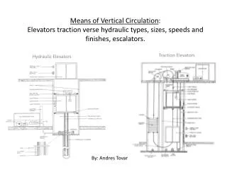
hydraulic machines. A hydraulic machine is a device in which mechanical energy is transferred from the liquid flowing through the machine to its operating member (runner, piston and others) or from the operating member of the machine to the liquid flowing through it .

E N D
A hydraulic machine is a device in which mechanical energy is transferred from the liquid flowing through the machine to its operating member (runner, piston and others) or from the operating member of the machine to the liquid flowing through it. • Hydraulic machines in which, the operating member receives energy from the liquid flowing through it and the inlet energy of the liquid is greater than the outlet energy of the liquid are referred as hydraulic turbines. • Hydraulic machines in which energy is transmitted from the working member to the flowing liquid and the energy of the liquid at the outlet of the hydraulic machine is less than the outlet energy are referred to as pumps. hydraulic machine
It is well known from Newton’s Law that to change momentum of fluid, a force is required. Similarly, when momentum of fluid is changed, a force is generated. This principle is made use in hydraulic turbine. In a turbine, blades or buckets are provided on a wheel and directed against water to alter the momentum of water. As the momentum is changed with the water passing through the wheel, the resulting force turns the shaft of the wheel performing work and generating power. A hydraulic turbine uses potential energy and kinetic energy of water and converts it into usable mechanical energy. The mechanical energy made available at the turbine shaft is used to run an electric power generator which is directly coupled to the turbine shaft The electric power which is obtained from the hydraulic energy is known as Hydroelectric energy. Hydraulic turbines belong to the category of Roto- dynamic machinery.
The hydraulic turbines are classified according to type of energy available at the inlet of turbine, direction of flow through vanes, head at the inlet of the turbines and specific speed of the turbines : According to the type of energy at inlet: Impulse turbine: - In the impulse turbine, the total head of the incoming fluid is converted in to a large velocity head at the exit of the supply nozzle. That is the entire available energy of the water is converted in to kinetic energy. Although there are various types of impulse turbine designs, perhaps the easiest to understand is the Pelton wheel turbine. It is most efficient when operated with a large head and lower flow rate.
Reaction turbine: Reaction turbines on the other hand, are best suited -for higher flow rate and lower head situations. In this type of turbines, the rotation of runner or rotor (rotating part of the turbine) is partly due to impulse action and partly due to change in pressure over the runner blades; therefore, it is called as reaction turbine. For, a reaction turbine, the penstock pipe feeds water to a row of fixed blades through casing. These fixed blades convert a part of the pressure energy into kinetic energy before water enters the runner. The water entering the runner of a reaction turbine has both pressure energy and kinetic energy. Water leaving the turbine is still left with some energy (pressure energy and kinetic energy). Since, the flow from the inlet to tail race is under pressure,casingis absolutely necessary to enclose the turbine. In general, Reaction turbines are medium to low-head, and high-flow rate devices. The reaction turbines in use are Francis and Kaplan
According to the direction of flow through runner: 1.. Tangential flow turbines: In this type of turbines, the water strikes the runner in the direction of tangent to the wheel. Example: Pelton wheel turbine. 2. Radial flow turbines: In this type of turbines, the water strikes in the radial direction. Accordingly, it is further classified as, a. Inward flow turbine: The flow is inward from periphery to the centre (centripetal type). Example: old Francis turbine. b. Outward flow turbine: The flow is outward from the centre to periphery (centrifugal type). Example: Fourneyronturbine. 3. Axial flow turbine: The flow of water is in the direction parallel to the axis of the shaft. Example: Kaplan turbine and propeller turbine. 4. Mixed flow turbine: The water enters the runner in the radial direction and leaves in axial direction. Example: Modern Francis turbine.
According to the head at inlet of turbine: High head turbine: In this type of turbines, the net head varies from 150m to 2000m or even more, and these turbines require a small quantity of water. Example: Pelton wheel turbine. Medium head turbine: The net head varies from 30m to 150m, and also these turbines require moderate quantity of water. Example: Francis turbine. (c) Low head turbine: The net head is less than 30m and also these turbines require large quantity of water. Example: Kaplan turbine. According to the specific speed of the turbine: (a) The specific speed of a turbine is defined as, the speed of a geometrically similar turbine that would develop unit power when working under a unit head (1m head). It is prescribed by the relation (b) Low specific speed turbine: The specific speed is less than 50. (varying from 10 to 35 for single jet and up to 50 for double jet ) Example: Pelton wheel turbine. Medium specific turbine: The specific speed is varies from 50 to 250. Example: Francis turbine. (d) High specific turbine: the specific speed is more than 250. Example: Kaplan turbine
GENERAL LAYOUT OF A HYDRO-ELECTRIC POWER PLANT A DAM THE PENSTOCK A WATER TURBINE TAIL RACE
Impulse Hydraulic Turbine : The Pelton Wheel Figure - Typical PELTON WHEEL with 21 Buckets The only hydraulic turbine of the impulse type in common use, is named after an American engineer Laster A Pelton, who contributed much to its development around the year 1880. Therefore this machine is known as Pelton turbine or Pelton wheel.
It is an efficient machine particularly suited to high heads. The rotor consists of a large circular disc or wheel on which a number (seldom less than 15) of spoon shaped buckets are spaced uniformly round is periphery. The wheel is driven by jets of water being discharged at atmospheric pressure from pressure nozzles. The nozzles are mounted so that each directs a jet along a tangent to the circle through the centres of the bucket. Down the centre of each bucket, there is a splitter ridge which divides the jet into two equal streams which flow round the smooth inner surface of the bucket and leaves the bucket with a relative velocity almost opposite in direction to the original jet.
WORK DONE & EFFICIENCY OF PELTON WHEEL V = absolute velocity u = bucket / blade velocity Vf = velocity of flow Vr = relative velocity Vw = Velocity of whirl Work Done = (Fx * u) = m. [ (Vw2 + Vw1 ) *u] And Power Developed (P) = W/1000 = m. [ (Vw2 + Vw1 ) *u] / 1000 kW
Hydraulic Efficiency of jet ηh= work done per second / K.E Supplied jet per second • ηh = 2 [ (Vw2 + Vw1 ) *u] / V12 • condition for maximum hydraulic efficiency • (ηh ) max = ( 1 + K cosϕ) / 2 , where K = friction factor • Mechanical Efficiency of jet ηm = Power available at turbine shaft / Power developed by runner • ηm= Ps / P • Volumetric Efficiency of jet ηv = Actual vol. of water striking the buckets / vol. of water issued by the jet • ηv= Qa / Q • Overall Efficiency of jet ηo = Power available at turbine shaft / Power available the water jet • ηo= Ps / Pi where Pi = ρ g Q H • ηo = ηv *ηh * ηm
Reaction Turbine: Francis Turbine The principal feature of a reaction turbine that distinguishes it from an impulse turbine is that only a part of the total head available at the inlet to the turbine is converted to velocity head, before the runner is reached. Also in the reaction turbines the working fluid, instead of engaging only one or two blades, completely fills the passages in the runner. The pressure or static head of the fluid changes gradually as it passes through the runner along with the change in its kinetic energy based on absolute velocity due to the impulse action between the fluid and the runner. Therefore the cross-sectional area of flow through the passages of the fluid A reaction turbine is usually well suited for low heads. A radial flow hydraulic turbine of reaction type was first developed by an American Engineer, James B. Francis (1815-92) and is named after him as the Francis turbine Figure - schematic diagram of a Francis turbine
A Francis turbine comprises mainly the four components: (i) spiral casing, (ii) guide on stay vanes, (iii) runner blades, (iv) draft-tube Figure - Components of Francis turbine Figure - Spiral Casing
GENERAL LAYOUT OF A REACTION TURBINE PLANT H = [ ( P / ρg) + (V2 /2g) + z ] penstock - [ ( P / ρg) + (V2 /2g) + z ] draft tube
Velocity Triangles, Work Done by water on runner and Efficiencies of Reaction turbine • Work done /s or Runner Power (W or P ) = ρ Q (Vw1 * U1 ± Vw2 * U2 ) • Hydraulic Efficiency of jet ηh= Power Developed by runner (P) / Power Input • ηh=ρ Q (Vw1 * U1 ± Vw2 * U2 ) / ρ g Q H • Mechanical Efficiency of jet ηm = Shaft power Ps / Power developed by runner P • Overall Efficiency of jet ηo = Shaft Power Ps / Input Power = ηh* ηm
Draft tube: The draft tube is a conduit which connects the runner exit to the tail race where the water is being finally discharged from the turbine. The primary function of the draft tube is to reduce the velocity of the discharged water to minimize the loss of kinetic energy at the outlet. This permits the turbine to be set above the tail water without any appreciable drop of available head. A clear understanding of the function of the draft tube in any reaction turbine, in fact, is very important for the purpose of its design. The purpose of providing a draft tube will be better understood if we carefully study the net available head across a reaction turbine. Different types of draft tubes incorporated in reaction turbines The draft tube is an integral part of a reaction turbine. The shape of draft tube plays an important role especially for high specific speed turbines, since the efficient recovery of kinetic energy at runner outlet depends mainly on it. Typical draft tubes, employed in practice, are discussed as follows. Figurer - Different types of draft tubes
Performance Characteristics of Reaction Turbine It is not always possible in practice, although desirable, to run a machine at its maximum efficiency due to changes in operating parameters. Therefore, it becomes important to know the performance of the machine under conditions for which the efficiency is less than the maximum. It is more useful to plot the basic dimensionless performance parameters Figure - Performance characteristics of a reaction turbine (in dimensionless parameters)
One of the typical plots where variation in efficiency of different reaction turbines with the rated power is shown. Figure - Variation of efficiency with load
Comparison of Specific Speeds of Hydraulic Turbines Figure shows the variation of efficiencies with the dimensionless specific speed of different hydraulic turbines. The choice of a hydraulic turbine for a given purpose depends upon the matching of its specific speed corresponding to maximum efficiency with the required specific speed determined from the operating parameters, namely, N (rotational speed), p (power) and H (available head). Figure - Variation of efficiency with specific speed for hydraulic turbines