Download
1 / 20
200 likes | 338 Views
Serial I/O. Programming Unit, Lecture 5. Serial I/O with the BASIC Stamp. The digital I/O examples have read or written a single bit of information, a switch being open or closed , an LED being on or off . Many applications require transferring groups of bits, bytes or words.

E N D
Serial I/O Programming Unit, Lecture 5 Serial I/O
Serial I/O with the BASIC Stamp The digital I/O examples have read or written a single bit of information, a switch being open or closed, an LED being on or off. Many applications require transferring groups of bits, bytes or words. Several of the digital I/O pins could be used in parallel for multi-bit I/O but this has the disadvantage of quickly running out of pins or increasing the complexity of the hardware with many wires or circuit board traces. An efficient alternative is to send many bits serially in time over a single wire or connection. This simplifies the hardware but does require software to manage the serial data stream. Serial I/O
Parallel Interface Data lines may be unidirectional or bi-directional. Width of data bus is usually byte-wide (8 data bits). A full byte of data is transferred on each R/W clock cycle. Chip Select (CS) allows multiple devices to share bus. Serial I/O
Serial Interface Asynchronous serial can be implemented with data lines only. Each device generates its own clock (Baud Rate Generator). Handshaking lines can be used to signal status of devices. Synchronous serial interfaces will have a separate Clock line. Clock is generated by a Master device. One bit is transferred for each clock cycle. Serial I/O
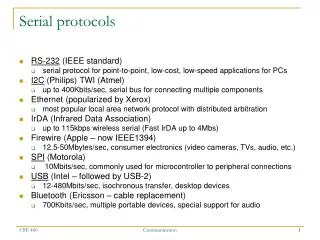
Synchronous and Asynchronous Serial Communication The BASIC Stamp communicates with the host PC through an asynchronous serial port, usually referred to as a serial port, comm port, or RS-232 port. The RS-232 standard specifies the communications protocol, voltage levels and signal wiring so that RS-232 devices can communicate with each other, at least most of the time. Modems, printers, video terminals and other devices frequently have asynchronous serial ports. Synchronous serial I/O is often used to interface specialized integrated circuits to the BASIC Stamp. Synchronous I/O uses a separate clock signal generated by the Master device (BASIC Stamp). Serial I/O
Asynchronous Serial Communication The RS-232 standard specifies logic levels that can typically exceed +10 or -10 volts. These levels can destroy a BASIC Stamp. Appropriate level conversion must be used to interface RS-232 devices to the I/O pins of the Stamp. USE CAUTION! The BASIC Stamp has a dedicated debug port which can safely connect to RS-232 but it is a simplified interface which may not work with all RS-232 devices. Serial I/O
Asynchronous Serial Communication Serial communication usually involves sending or receiving “characters” using the ASCII code. For example the character “S” is represented by the binary number “01010011” or 53 in hexadecimal. An asynch transmission of “S” begins with a start bit, followed by 8 data bits and ending with a stop bit. There are numerous options for number data bits, speed and an optional parity bit. Serial I/O
Using the SEROUT Command • The SEROUT command is used to send serial data. Any of the I/O pins P0 through P15 can be used for serial data. In addition the BASIC Stamp BS2P has the dedicated DEBUG port for downloading and debugging programs on the host PC. The Debug port can be referred to as logical port P16 and corresponds to physical pin 1, called SOUT. • Syntax for the simplest use of SEROUT: • SEROUT pin, Baudmode, [Outputdata] • For example SEROUT P4, 16468, [“Testing”] • This would send the stream of ASCII characters Testing out of I/O logical pin 4. See the PBASIC Help on SEROUT command for details. The above command sets the communication speed to 9600 baud (~bits per second). • The DEBUG command automatically uses P16 at 9600 baud. Serial I/O
Using the SERIN Command • Like the SEROUT command, the SERIN command is for asynchronous serial I/O but in this case is for receiving data by the BASIC Stamp. The I/O pins can be set to P0 through P15 or to the Debug port. • The simplest usage of SERIN is • SERIN pin, Baudmode, [InputData] • SERIN has powerful optional features for waiting on input data, filtering and formatting the received data. See the PBASIC Help on SERIN for details. • One possible application using SERIN would be receiving data from a Global Positioning System (GPS) module which typically defaults to asynchronous data at 4800 baud. Serial I/O
Synchronous Serial I/O Synchronous serial I/O uses a separate line for a CLOCK signal. The voltage levels used for the synchronous serial clock and data lines are the TTL logic levels that are native to the BASIC Stamp so no level converters or line drivers/receivers are required. There are several protocols in use. Some use a bi-directional data line while others use separate Data-In and Data-Out lines. The Master generates the clock and initiates and controls data transfer. Serial I/O
The I2C Bus • Inter-Integrated-Circuit or I2C (pronounced I-too-see or I-squared-see) is a synchronous serial protocol that uses a bi-directional data line and supports multiple slave devices controlled by a I2C bus master. • Defined by Phillips Semiconductor and became an industry standard. • The clock line is called SCL, the data line SDA Serial I/O
The I2C bus master generates SCL and initiates communication with one of the slave devices. Each device has a unique address for device selection. • A device address can be a combination of bits that are “hard-wired” into the chip design and one or more pins on the device. These pins can be wired High or Low to select an address that doesn’t conflict with other devices on the I2C bus. • Pull-up resistors are required on both the clock and data lines. • A variety of special function integrated circuits are available with I2C interfaces, including memory chips, analog-to-digital converters, digital-to-analog converters and real-time-clocks. Serial I/O
I2C START and STOP • A START sequence begins a bus transmission by transitioning SDA from High to Low while SCL is High. • A STOP sequence ends a transmission. The Stop sequence occurs when the master brings SDA from Low to High while SCL is High. Serial I/O
I2C Write Sequence • A typical I2C bus sequence for writing to a slave: • Send a START sequence • Send the I2C device address with the R/W Low (for Write) • Send the data byte • Optionally send additional data bytes (after repeating START) • Send the STOP sequence after all data bytes have been sent • The Slave responds by setting the ACK bit (Acknowledge) Serial I/O
I2C Read Sequence • Reading an I2C Slave device usually begins by writing to it. You must tell the chip which internal register you want to read. • I2C Read Sequence • Send the START condition • Send the device address with R/W held Low (for a Write) • Send the number of the register you want to read • Send a repeated START condition • Send the device address with R/W set High (for a Read) • Read the data byte from the slave • Send the STOP sequence Serial I/O
I2C Read example using device address 1100000 and reading register number 1. Serial I/O
I2C Programming on the BASIC Stamp The BASIC Stamp can be programmed to operate as an I2C bus master by “brute force” using the HIGH and LOW instructions but PBASIC provides several instructions designed to make synchronous serial and I2C communications less tedious. The I2CIN and I2COUT instructions do most of the low level dirty work of properly sequencing the SDA and SCL signals, but only a subset of the I/O pins can be used for the I2C bus physical layer. If I/O pin P0 is selected to be SDA, then SCL is I/O pin P1. If I/O pin P8 is selected to be SDA, then SCL is I/O pin P9. The I2C instructions work with only these two pin configurations. Serial I/O
The I2COUT Instruction Syntax: I2COUT pin, slaveID, address, OutputData pin specifies SDA and can only be 0 or 8. SCL will then be pin 1 or 9. slaveID is the slave device address address is the register address within the slave device OutputData is the data to write to the I2C slave device The I2COUT instruction automatically sets the R/W bit. The I2COUT instruction supports multiple address bytes which may be required for some slave devices. See the PBASIC Help for details. Serial I/O
The I2CIN Instruction Syntax: I2CIN pin, slaveID, address, InputData pin specifies SDA and can only be 0 or 8. SCL will then be pin 1 or 9. slaveID is the slave device address address is the register address within the slave device InputData is the data read from the I2C slave device The I2IN instruction automatically sets the R/W bit. The I2IN instruction supports multiple address bytes which may be required for some slave devices. See the PBASIC Help for details. Serial I/O
Other Synchronous Serial Protocols • Several IC manufacturers have developed their own protocols for synchronous serial communication. The data sheets and application notes from the chip manufacturer should be consulted for design and troubleshooting tips. • A few popular serial I/O protocols • MICROWIRE (National Semiconductor) • SPI (serial peripheral interface from Motorola) • OneWire (Dallas Semiconductor) Serial I/O