192.168.0.0/30
150 likes | 636 Views
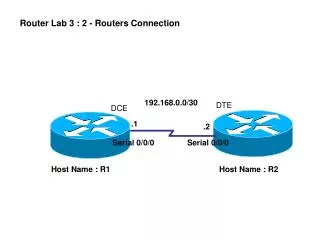
Router Lab 3 : 2 - Routers Connection. 192.168.0.0/30. DTE. DCE. .1. .2. Serial 0/0/0. Serial 0/0/0. Host Name : R1. Host Name : R2. Router Lab 4 : Basic Static Route. DTE. DCE. 192.168.0.0/30. .1. .2. R2. R1. Serial 0/0/0. Serial 0/0/0. F0/0. .1. F0/0. .1. 192.168.2.0/24.

192.168.0.0/30
E N D
Presentation Transcript
Router Lab 3 : 2 - Routers Connection 192.168.0.0/30 DTE DCE .1 .2 Serial 0/0/0 Serial 0/0/0 Host Name : R1 Host Name : R2
Router Lab 4 : Basic Static Route DTE DCE 192.168.0.0/30 .1 .2 R2 R1 Serial 0/0/0 Serial 0/0/0 F0/0 .1 F0/0 .1 192.168.2.0/24 192.168.1.0/24 .2 .2 PC1 GW:192.168.1.1 PC2 GW:192.168.2.1
Router Lab 5 : Static Route and Default Route Host Name : R1 Host Name : R2 Host Name : R3 192.168.0.0/30 192.168.3.0/30 DCE DCE DTE DTE .1 .1 .2 .2 Serial 0/1/0 Serial 0/0/0 Serial 0/0/0 Serial 0/0/0 F0/0 .1 .1 F0/0 F0/0 .1 192.168.2.0/24 192.168.1.0/24 192.168.4.0/24 .2 .2 .2 PC1 GW:192.168.1.1 PC2 GW:192.168.2.1 PC3 GW:192.168.4.1
R2(config) router rip R2(config-router)# network 192.168.0.0 R2(config-router)#network 192.168.2.0 R2(config-router)#network 192.168.3.0 Host Name : R1 Host Name : R3 Host Name : R2 192.168.0.0/24 192.168.3.0/24 .1 .1 .2 .2 Serial 0/0/0 Serial 0/1/0 Serial 0/1/0 Serial 0/1/0 .1 .1 .1 192.168.2.0/24 192.168.1.0/24 192.168.4.0/24 .2 .2 .2 R3(config) router rip R3(config-router)# network 192.168.3.0 R3(config-router)#network 192.168.4.0 R1(config) router rip R1(config-router)# network 192.168.1.0 R1(config-router)#network 192.168.0.0 Dynamic Route [RIP]
R1(config) router ospf 1 R1(config-router)# network 192.168.4.0 0.0.0.255 area 0 R1(config-router)# network 192.168.3.0 0.0.0.255 area 0 OSPF Area 0 Host Name : R1 Host Name : R3 Host Name : R2 192.168.0.0/24 192.168.3.0/24 .1 .1 .2 .2 Serial 0/0/0 Serial 0/1/0 Serial 0/1/0 Serial 0/1/0 .1 .1 .1 192.168.2.0/24 192.168.1.0/24 192.168.4.0/24 .2 .2 .2 R1(config) router ospf 1 R1(config-router)# network 192.168.1.0 0.0.0.255 area 0 R1(config-router)#network 192.168.0.0 0.0.0.255 area 0 Dynamic Route [OSPF]
192.168.0.0/24 .3 .4 F0/3 F0/4 2960 F0/1 F0/2 192.168.0.0/24 .1 .2 #int fast Ethernet 0/1 #switchport mode access
10.1.1.0/24 Native VLAN 1 10.1.10.0/24 Admin VLAN 10 Ports:1-8 Catalyst 2960 Ports:16-24 Ports:9-15 10.1.20.0/24 Accounting VLAN 20 10.1.30.0/24 Engineering VLAN 30
SW1 Vlan 2 – sale Vlan3 - engineering Gi1/2 Gi1/1 IEEE 802.1q Trunk IEEE 802.1q Trunk Gi1/1 Gi1/1 SW3 SW2 F0/2 F0/2 F0/1 F0/1 Vlan 2 192.168.2.2 Vlan 3 192.168.3.2 Vlan 2 192.168.2.1 Vlan 3 192.168.3.1
Vlan 2 – sale Vlan3 – engineering Vlan4 – guest Server SW1 IEEE 802.1q Trunk IEEE 802.1q Trunk IEEE 802.1q Trunk SW3 SW4 SW2 Client Transparent Client IEEE 802.1q Trunk IEEE 802.1q Trunk SW5 SW6 Client Client Domain : Cyber Password : cisco
Vlan 2 :: 192.168.2.1 Vlan 3 :: 192.168.3.1 VLAN 3 192.168.3.0/24 2960 F0/2 3560 G1/1 G1/1 .2 F0/1 .2 VLAN 2 G1/2 192.168.2.0/24 G1/1 2960 VLAN 3 F0/2 192.168.3.0/24 F0/1 .3 .3 Trunk Line VLAN 2 VTP Domain : yru VTP Server : ws-c3560 VTP Client : ws-c2960 192.168.2.0/24
Host Name : ISP S0/1/0 DCE 192.31.7.5/30 S0/1/0 192.31.7.6/30 fa0/0 – no IP address fa0/0.1 – VLAN1(Native) – 192.168.1.1/24 fa0/0.10 – VLAN10 – 192.168.10.1/24 fa0/0.20 – VLAN20 – 192.168.20.1/24 fa0/0.30 – VLAN30 – 192.168.30.1/24 Host Name : CORP IEEE 802.1q Trunk Fa0/1 VLAN1 192.168.1.2/24 Sales VLAN 10 Fa0/2-4 192.168.10.0/24 Engineering VLAN 20 Fa0/5-8 192.168.20.0/24 Marketing VLAN 30 Fa0/9-12 192.168.30.0/24 Native VLAN 1 Fa0/1 192.168.1.0/24 192.168.10.10/24 192.168.20.20/24 192.168.30.30/24
Cisco configuration of DHCP service on a Router or L3 Switch Network subnet : 192.168.0.0 255.255.255.0 Gateway Address : 192.168.0.1 DNS Server : 4.2.2.2 Excluded Addresses : 192.168.0.1 to 192.168.0.10 R1 .1 192.168.0.0/24
Cisco configuration of DHCP service on a Router or L3 Switch Network subnet : 192.168.0.0 255.255.255.0 Gateway Address : 192.168.0.1 DNS Server : 4.2.2.2 Excluded Addresses : 192.168.0.1 to 192.168.0.10 #ip dhcp pool mypool #network 192.168.0.0 255.255.255.0 #default-router 192.168.0.1 #dns-server 4.2.2.2 #exit #ip dhcp excluded-address 192.168.0.1 192.168.0.10 R1 .1 192.168.0.0/24
NAT – Network Address Translation Internet 99.99.99.99/24 FA0/1 R1 FA0/0 .1 192.168.1.0/24 .10 .7 .8
PAT – Port Address Translation Internet 99.99.99.99/24 FA0/1 R1 FA0/0 .1 192.168.1.0/24 ip nat inside source list 1 interface FastEthernet0/1 overload access-list 1 permit 192.168.1.0 0.0.0.255 interface FastEthernet0/0 ip address 192.168.1.1 255.255.255.0 ip nat inside interface FastEthernet0/1 ip address 99.99.99.99 255.255.255.0 ip nat outside .7 .8