Download
1 / 58
710 likes | 1.41k Views
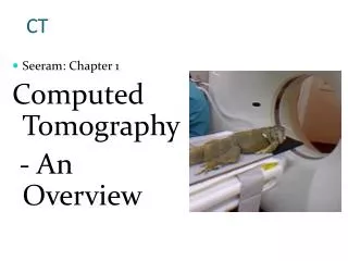
CT. Seeram: Chapter 1 Computed Tomography - An Overview. Early History. “ tomos ” Greek word meaning section Sectional imaging methods first developed in 1920’s. Early History: Conventional Tomography. first used in 1935 image produced on film Image plane oriented parallel to film

E N D
CT • Seeram: Chapter 1 Computed Tomography - An Overview
Early History • “tomos” • Greek word meaning section • Sectional imaging methods first developed in 1920’s
Early History:Conventional Tomography • first used in 1935 • image produced on film • Image plane oriented parallel to film • Anatomy in plane of fulcrum stays in focus • anatomy outside of fulcrum plane mechanically blurred
Conventional vs Axial Tomography Conventional Cut CT Axial Cut
Conventional Tomography Blurring • Image produced on film • Objects above or below fulcrum plane change position on film & thus blur
CT Image • Not produced on film • Mathematically reconstructed from many projection measurements of radiation intensity • Digital Image calculated Acme Mini- Compu- ter Digital Image
The story concerns these men. What was their Link? ??? Geoff Paul, Ringo, George, & John
Measure Intensity of a Pencil Beam X-Ray Source Radiation Detector
CT Image • Measure a bunch of pencil beam intensities
CT Image • Now make measurements from every angle
CT Image • When you get done, multiple pencil beams have gone through every point in body
Image Reconstruction X-Ray Source Acme Mini- Computer Pixel (calculated) Data Radiation Detector Projection (raw) Data
Digital Image • 2-dimensional array of individual image points calculated • each point called a pixel • picture element • each pixel has a value • value represents x-ray transmission (attenuation)
125 25 311 111 182 222 176 199 192 85 69 133 149 112 77 103 118 139 154 125 120 145 301 256 223 287 256 225 178 322 325 299 353 333 300 Digital Image Matrix
Numbers / Gray Shades • Each number of a digital image corresponds to a gray shade for one pixel
Image Reconstruction • CT math developed in 1910’s • Other Applications • astronomy (sun spot mapping) • electron microscope imaging • Nuclear medicine emission tomography • MRI
CT History • First test images in 1967 • First clinical images ~ 1971 • First commercial scanner 1972
CT History • CT math developed in 1910’s • First commercial scanner 1972 • What took so long?
CT History • CT made possible by high speed minicomputer
CT Computers • Old mainframe computers too expensive & bulky to be dedicated to CT
CT history - Obsolete Terminology • CTAT • computerized transverse axial tomography • CAT • computerized axial tomography • CTTRT • computerized transaxial transmission reconstructive tomography • RT • reconstructive tomography
Data Acquisition • cross sectional image reconstructed from many straight line transmission measurements made in different directions Tube Detector
CT Early Units • 4 minute scans • 5 minute reconstruction • 80 X 80 matrix • head only • water bag fit tightly around head
X-ray Tube Detector Beam Translation • beam collimated to small round spot • collimated at tube and collimator
X-ray Tube Detector Beam Translation • Tube/detector translates left to right • Entire assembly rotates 1o to right • Tube/detector translates right to left
Translate - Rotate • 180 translations in alternate directions • 1 degree rotational increments between translations
Projection Measurements • Radiation detector generates a voltage proportional to radiation intensity
Image Reconstruction Analog to Digital (A to D) conversion • Minicomputer does its thing
125 25 311 111 182 222 176 199 192 85 69 133 149 112 77 103 118 139 154 125 120 145 301 256 223 287 256 225 178 322 325 299 353 333 300 Digital Image Matrix • Digital Matrix contains many numbers which may be • Displayed on CRT • Manipulated • Stored
Digital Image Manipulation • Window • Level • Smoothing • Edge enhancement • Slice reformatting • 3D • derived from multiple axial slices
Digital Image Storage • Magnetic Disk • CD • Tape • Optical Disk • PACS archive • picture archival and communications system • not part of CT • contains images from many modalities • allows viewing on connected computers
CT - Improvements • all CT generations measure same multi-line transmission intensities in many directions • Improvements • Protocol for obtaining many line transmissions • # of line transmissions obtained simultaneously • detector location • Overall acquisition speed
2nd Generation CT Tube • arc beam used instead of pencil beam • several detectors instead of just one • detectors intercepted arc • radiation absorbent septa between detectors • reduced scatter • acted like grid Detectors
2nd Generation CT 10o • arc beam allowed 10 degree rotational increments • scan times reduced • 20 sec - 2 min • 2 slices obtained simultaneously • double row of detectors
3rd Generation CT • Wide angle fan beam • rotational motion only / no translation • detectors rotate with tube • 30o beam • Many more detectors • scan times < 10 seconds
3rd Generation CT Z-axis orientation perpendicular to page Patient
4th Generation CT • Fixed annulus of detectors • tube rotates (no translation) inside stationary detector ring • only a fraction of detectors active at once
3rd & 4th Generation (Non-spiral) CT • Tube rotates once around patient • Table stationary • data for one slice collected • Table increments one slice thickness • Repeat • Tube rotates opposite direction
3rd / 4th Generation Image Quality Improvements • Faster scan times • reduces motion artifacts • Improved spatial resolution • Improved contrast resolution • Increased tube heat capacity • less wait between scans / patients • better throughput
Spiral CT • Continuous rotation of gantry • Patient moves slowly through gantry • cables of old scanners allowed only 360o rotation (or just a little more) • tube had to stop and reverse direction • no imaging done during this time • no delay between slices • dynamic studies now limited only by tube heating considerations
Spiral CT Z-axis orientation perpendicular to page Patient
Multi-slice CT • Multiple rows of fan beam detectors • Wider fan beam in axial direction • Table moves much faster • Substantially greater throughput
Computer Improvements • Reconstruction time • Auto-printing protocols • Image manipulation • Backup time • Slice reformatting • 3D reconstruction And the ability to do it all simultaneously
Cine CT (Imatron) • four tungsten target rings surround patient • replaces conventional x-ray tube • no moving parts • like 4 moving focal spots • electron beam sweeps over each annular target ring • can be done at electronic speeds • 2 detector rings • 2 slices detected • maximum scan rate • 24 frames per second