Total view
Total view. Overall detector view. One axis. Horizontal motion overview. H. K. NI. EF. Horizontal motion limits. Beam center line = 0. Overlap = 5mm. SS=29.7 RS=29.8 ES=30.0 HS=30.2. SS=-0.1 ES=-0.2 HS=-0.4. X. STOP. STOP. STOP. STOP. STOP. STOP. STOP. X. L. STOP.
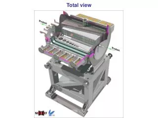

Total view
E N D
Presentation Transcript
H K NI EF Horizontal motion limits Beam center line = 0 Overlap = 5mm SS=29.7 RS=29.8 ES=30.0 HS=30.2 SS=-0.1 ES=-0.2 HS=-0.4 X STOP STOP STOP STOP STOP STOP STOP X L STOP STOP STOP STOP STOP STOP STOP HS=-0.4 ES=-0.2 SS=-0.1 HS=30.2 ES=30.0 RS=29.8 SS=29.7 HS = hardstop (mm) ES = endswitch (mm) RS = reference switch (mm) SS = software stop (mm)
H K NI EF Vertical motion limits HS=5.2 ES=5.0 RS=4.8 SS=4.7 STOP STOP STOP STOP up down beam center = 0 SS=-4.9 ES=-5.0 STOP STOP detector mounting = -7 HS = hardstop (mm) ES = endswitch (mm) RS = reference switch (mm) SS = software stop (mm) bellow mounting = -20
H K NI EF Block diagram 60 meter Target area Service area Control system ES,RS ES switchinterf. Rs232 stepperinterf. res.interf. resolver stepperm. Cp340 U33 40:1 Hardware interlocks spindle XR Dig out Beam safety system step.drive Sm322 potm.interf. PotentiometerP1, P2, P3 Rs232 Cp340 3x ES,RS ES To scada system switchinterf. Control system stepperinterf. res.interf. Ethernet resolver stepperm. Cp343 192.16.192.50 U33 40:1 spindle XL step.drive Processor potm.interf. CPU 316-2DP PotentiometerP1, P2, P3 Ana in ES Sm331 2x 16 chann. ES,RS switchinterf. portableoperatordisplay stepperinterf. res.interf. Dig in/out resolver stepperm. Sm323 U33 16:1 Power supply spindle Y step.drive PS307-5 potm.interf. Plug-in at service- or target area PotentiometerP1, P2, P3, P4 Dig in Sm321 32 chann. UPS
H K NI EF PLC variables for one axis ES,RS ES switchinterf. stepperinterf. res.interf. resolver stepperm. U33 40:1 spindle XR step.drive potm.interf. PotentiometerP1, P2, P3 Read variables; resolution range conv. to position P1 Value during movement 16bit 0…5V 0 - 50.00mm P2 Value during movement 16bit 0…5V 0 - 50.00mm P3 Value during movement 16bit 0…5V 0 - 50.00mm Write; Z to set reference to stepper interface A nnn move to position to stepper interface P read stepper value to stepper interface L read resolver value to stepper interface Q emergency stop for stepper to stepper interface M master mode bit to switch interface Read variables; Stepper value after movement resolution range conv. to position Resolver value after movement 10bit 0…xx 0..mm ES status out for each sub axis 1bit 1=active RS status as reference 1bit 1=active ES status in for each sub axis 1bit 1=active Stepper driver status 1bit 1=ok
H K NI EF PLC initial procedure start init • At start; • First check mode to establish the right communication? • Or always in physics mode? • Check or this command is allowed? • A priori out of reference • Inhibit beam injection • Goto reference position • Error 101 on time out +? (other procedure) • Enable beam injection • Goto desired position (other procedure) • So far it means that there is possible a beam without knowing the position of the detector? • Procedure delivers a status flag that all values are referenced? status check n physics mode out of reference physics mode n master limitsactive physics limitsactive disable beaminjection Zcommand ready n time out n Set reference values error105 error101 Goto main-loop enable beaminjection stop
H K NI EF PLC mode procedure • Physics mode or Master mode. • Status are presented to SCADA and portable display • Physics mode: • Accept only commands via SCADA system • Narrower limits then master mode • No password protection • No change allowed of the mode • Master mode: • Accept only commands by portable display • More limit privileges then physics mode • Only via password protection changing of mode
H K NI EF PLC Main Loop start main At start; Only allowed if values are referenced? Mode depends on mode procedure During movement injection inhibit? Stepper drive power on? physics mode n master limitsactive physic limitsactive Positionnnn read pos. error103 calculation desired Pos. Calc.time-out value Stepper position n Pos. < limits Resolverposition Statusloop disable beaminjection Potmeterposition A nnncommand n Check potm. ready n n time out enable beaminjection error102 error101 Statusloop End
H K NI EF PLC Status loop start status start status Select Axis XL-XR-Y Get XL sw Get XR sw Get Y sw Read position stepper Store data Read position resolver Store data Send P Send L Switch XL error Tolerance +/- 25 steps Switch XR error Switch Y error With potentiometer table Compare Switch status ok Status ok Error 104
H K NI EF Error xx Error101 Error102 Error101;Has to end with Q command? Error 101, 102;Back to ref. Pos.?Enable beam inj.? Error 103 Send to PVVS “Input?” Error 104 Send to PVVS “Axis undefined pos” Time out Position inconsistentlyGive status To scada and display Error103 Error104 Input error Axis pos. error
DSLpx XL XL DSRsw1y USLsw1y DSLsw1y Y USRsw1y USLpy DSLpy DSRpy USRpy Box6 Box5 DSLsw2y USLsw2y DSRsw2y USRsw2y Ref sw. H K NI EF Frame parts Downstream DSRpx Bottom DSLsw2x DSRsw1x DSLsw1x USRTpx USLTpx USLTsw2x Top USRTsw1x USLTsw1x USLsw1x USRsw1x USRsw2x USRpx USRpx Ref sw. Ref sw. Bottom XR Upstream Top Top XR Top Box4 Box3 USLTsw1x USRsw1x Downstream Left Right Upstream Upstream Downstream Ref sw. USLsw1x DSRsw1x DSLsw1x USRsw1x Bottom Ref sw. Box1 Box2 Box2 Bottom Bottom
H K NI EF Commands Available commands to the stepper interface; XL XR Y Z Annn P L Q goto reference position (takes 300 seconds maximum for XL and XR or 30 seconds for Y axis)check moving with the potentiometers goto nnn absolute postition (takes 300 seconds maximum for XL and XR or 30 seconds for Y axis) nnn in steps, value between 0 and 1.400.000 (35.00mm) check moving with the potentiometers read the position of the stepper read the actual value of the resolver equal on the stepper (+/- 25 steps) quit the command (Z and A), stops the steppermotor.
H K NI EF Variable list 1 Variable layout; Nickname symbol address datatype value comment Global variable for the XL detector half; Symbol address data type value comment XL-axis-mm xx xx variable XL-axis distance in mm XL-axis-resolver xx xx XL-axis distance in resolver steps XL-axis-steps xx xx XL-axis distance in steppermotor steps XL-res-ref-position xx xx constant
H K NI EF Variable list 2
H K NI EF Variable list 3
OLD Motion control PLC System Motion Controls Stepper and resolver controller 3x Switch Power Hardware interlocks interface steppermotor to the beam inhibit STEPPER system DRIVE 3x resolver RS232 RESOLVER DIG I/O interface ADC Potmeter RS232 Ethernet Potmeter interface CPU ethernet Shielding wall Power Supply To scada system PVSS II PLC Siemens hand control S7-300 hand control panel