Download
1 / 21
210 likes | 386 Views
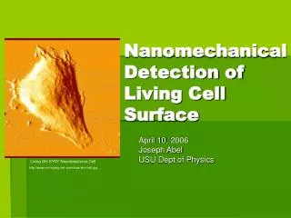
Nanomechanical Detection of Living Cell Surface. April 10, 2006 Joseph Abel USU Dept of Physics. Living SH-SY5Y Neuroblastoma Cell http://www.uni-leipzig.de/~pwm/kas/afm/cell.jpg. www.ub.es/biofisica/images/beas2b.jpg . Human Bronchial Epithelial Cells. Atomic Force Microscopy .

E N D
Nanomechanical Detection of Living Cell Surface April 10, 2006 Joseph Abel USU Dept of Physics Living SH-SY5Y Neuroblastoma Cell http://www.uni-leipzig.de/~pwm/kas/afm/cell.jpg
www.ub.es/biofisica/images/beas2b.jpg Human Bronchial Epithelial Cells Atomic Force Microscopy http://www.deutsches-museum.de/dmznt/remote_lab/hintergrundafm/mikroskope/rastersondenmikroskop/ DNA Biological systems can only be fully understood if there physical structure is known. Atomic Force Microscopy allows for the micro/nano scale measurements of the topography of the surface of biological samples in there native environments.
Basic Atomic Force Microscopy An Atomic Force Microscope makes nano-scale measurements of surfaces by using a cantilever with a tip attached that detects the surface of the object being imaged. Movement of the tip is translated into an image of the surface of the object. There are various methods developed to detect the motion of the tip. In the picture above a laser beam is used. This is the most common method. There are also various methods used to image the surface of the object.
http://www.nanoscience.com/education/AFM.html Imaging Modes The Force on the cantilever is used to measure the topography of the image. The force comes from Van der Waal forces and electrostatic forces. There are many ways a cantilever can by used to image the forces on the surface of a sample. These Forces are then generated into topographic images of the surface. Some examples of the modes used are: Contact Mode Non-Contact Mode • Contact Mode • Non-contact Mode • Tapping
In Constant Force mode the force, or bending in the cantilever remains constant. The cantilever height is adjusted to keep the force the constant. Procedures in Scanning Probe Microscopies, John Wiley & Sons, 1998 Constant Height In Constant Height mode the height of the cantilever is kept constant. Procedures in Scanning Probe Microscopies, John Wiley & Sons, 1998 Contact Mode Constant Force
AFM Image Signal for Constant Force/Height Constant Force The AFM has two standard ways to measure the topography of a sample. One way is by the feedback output, the other is by the cantilever deflection (error signal). The sum of the two signal yields the actual topography of the surface Constant Height Procedures in Scanning Probe Microscopies, John Wiley & Sons, 1998
Images Formed by Contact Mode http://www.biophysik.uni-bremen.de/radmacher/publications/cardiocytes.html Chicken Cardiomyocyte http://www.che.utexas.edu/georgiou/Research/Bacterial_Adhesion.htm A Contact-mode AFM image of an Escherichia coli bacterial lawn irreversibly immobilized onto a planar glass surbstrate under physiological conditions
http://edoc.hu-berlin.de/dissertationen/samori-paolo-2000-10-24/HTML/samori-ch2.htmlhttp://edoc.hu-berlin.de/dissertationen/samori-paolo-2000-10-24/HTML/samori-ch2.html Non-Contact Imaging Non-Contact mode measure the topography by oscillating the cantilever. The amplitude of the oscillation determines the images. The cantilever is set a control oscillation before reaching the surface. Once reaching the surface changes in amplitude are made by the attractive forces on the surface. Non-Contact mode is used for imaging samples that may be damaged by contact mode.
http://edoc.hu-berlin.de/dissertationen/samori-paolo-2000-10-24/HTML/samori-ch2.htmlhttp://edoc.hu-berlin.de/dissertationen/samori-paolo-2000-10-24/HTML/samori-ch2.html Tapping Mode Tapping Mode is similar to Non-Contact Mode. Both use the amplitude of oscillation to measure the topography of the surface. The difference come in the method the tip travels over the surface. In Tapping Mode the tip is lowered until contact with the surface is made, unlike non-contact mode. Tapping Mode limits the amount of damage done to the surface being imaged. The Phase of the oscillation can be used to discriminate between different materials on the surface
http://www.astbury.leeds.ac.uk/facil/SPM/SPM.htm Micron phase image of material lifted from a section of human brain tissue Images Formed By Tapping mode http://www.astbury.leeds.ac.uk/facil/SPM/SPM.htm Tapping mode AFM image of a fibril formed by the aggregation of the protein, b2M (Scale bar is 200 nm)
Cantilever Deflection Sensors To be able to image the surface, some senor most be used to detect changes in the cantilever. Different methods have been developed to measure the cantilevers movement. The Beam Deflection Method is the most common used today. Although the piezo methods show definite promise for the future. Procedures in Scanning Probe Microscopies, John Wiley & Sons, 1998
Electron Tunneling Deflection Sensors Binnig, Quate. Atomic Force Microscope, Physical Review Letters, 1986 In 1986 an electron tunneling deflection sensor was introduced to measure the deflection of an AFM tip. The basic setup is an Scanning Tunneling Microscope (STM) mounted above the AFM tip. The STM then measures the electron tunneling between the STM tip and the AFM tip. This setup is used because the STM can only measure conductive and semiconductive surfaces. The methods works best in a Ultra-High Vacuum, which is not possible for biological samples.
Capacitance Deflection Sensors Gabi, Cohen, McClelland, Horne, Mate. Force Microscopy with Bidirectional Capacitance Sensor. Rev. Sci. Instruments, 1990 In the above example, the deflection of the cantilever is measured by the change in capacitance between two parallel plates and the cantilever. When the distance between the plates is change so is the capacitance, therefore the distance can be calculated from the change in capacitance. Because two plates are used, Friction can be measured. Friction will cause a twisting in the cantilever, making one of the two plates closer than the other. The difference in capacitance of the two plates can be used to determine the Friction Force.
Beam Deflection Sensors In Beam Deflection Sensors a Laser is aimed at a reflective surface on the back of the cantilever. The laser is then deflected to a position detector. This is the most commonly used detection system today Meyer, Amer. Novel optical approach to atomic force microscopy. Appl. Phys. Lett. 53, 1045 (1988)
Interferometer Deflection Sensor Rugar, Mamin, Gunthner. Improved fiber-optic interferometer for atomic force microscopy. Applied Physics Letters, 1989, 52, 2588. In the interferometer method a laser beam is aimed through a directional coupler, where it is split equally between leads 2 and 3. Lead 3 goes to a reference photodiode. In lead 2 approximately 4% of the light is reflected from the cleaved end of the fiber optic. The other 96% strike the cantilever surface and some reflect back into the fiber optic and interfere with the 4% of light that was reflected. The total power reflected back through the fiber optic depend on phase difference between the light reflected from the end of the fiber optic and the light reflected from the cantilever. Half of the light traveling back through the fiber optic is redirected to lead 4, and used as the signal for the cantilever.
Piezoresistive Deflection Sensors In piezoresistive deflection sensors, a piezoresistive material is micro machined directly into the cantilever. To detect the changes in the cantilever a current is run through the cantilever and detected by a Wheatstone bridge. (See Figures A and B). This method simplifies greatly the alignment process. (There is none) It is also very useful for large surface areas. Tortonese, Barrett, Quate. Atomic resolution with an atomic force microscope using piezoresistive detection. Appl. Phys. Lett, 1993, 62, 834.
Piezoelectric Deflection Sensor Piezoelectric Deflection Sensors are based on piezo electricity. They are constructed of thin films of various piezo-electric materials. • Advantages • No external detection system. This simplifies the design of detection systems, especially for large area images and images immersed in liquid • Precise alignment of deflection components is not needed. Lee, Itoh, Suga. Micromachined Piezoelectric Force Sensors Based on PZT Thin Films. IEEE TRANSACTIONS ON ULTRASONICS, FERROELECTRICS, AND FREQUENCY CONTROL, VOL. 43, NO. 4, JULY 1996
Methods in Measuring Biological Samples Substrate Selection “The specimen must be supported on some sort of solid substrate in order to be imaged by AFM. The ideal substrate should be atomically flat, without any intrinsic surface features. This is essential in order to avoid misinterpretation of the images due to a confusion between substrate corrugations and surface structures of adsorbed macromolecules. Furthermore, the substrate must also have adequate interactions with the adsorbed macromolecules, so that they are not displaced by the scanning tip or do not float off in a buffer solution. Preferentially, the molecules should remain functional, at least partially. This latter requirement indicates that the surface interaction should not be excessively strong, in which case the structure would be seriously deformed; this could in turn be another source of artefacts.” Shao, Mou, Czajkowsky, Yang, Yuan. Biological atomic force microscopy: what is achieved and what is needed. Taylor & Francis, Volume 45, Number 1 / January / February 1996
Procedures in Scanning Probe Microscopies, John Wiley & Sons, 1998 Methods in Measuring Biological Samples Measuring in Liquids Measuring biological samples in liquid allows for in situ imaging. The adhesion forces are also reduced thus making it possible to image soft organic matter, that would otherwise be destroyed. Basic Setup
http://www.bfrl.nist.gov/nanoscience/BFRL_AFM.htm Methods in Measuring Biological Samples Functionalized Tips AFM tips have had specific molecules and proteins added. This allows for the measurement of the interaction between the surface and the particular proteins or molecules. http://www.biologicalprocedures.com/bpo/arts/1/67/m67f2lg.htm