Download
1 / 43
860 likes | 1.9k Views
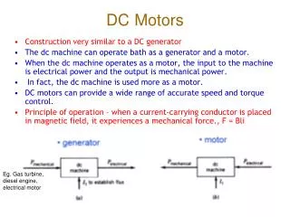
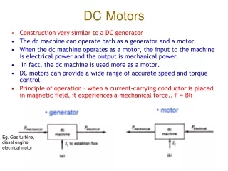
DC Motors. DC Motor. The direct current (dc) machine can be used as a motor or as a generator. DC Machine is most often used for a motor. The major advantages of dc machines are the easy speed and torque regulation.

E N D
DC Motor • The direct current (dc) machine can be used as a motor or as a generator. • DC Machine is most often used for a motor. • The major advantages of dc machines are the easy speed and torque regulation. • However, their application is limited to mills, mines and trains. As examples, trolleys and underground subway cars may use dc motors. • In the past, automobiles were equipped with dc dynamos to charge their batteries.
DC Motor • Even today the starter is a series dc motor • However, the recent development of power electronics has reduced the use of dc motors and generators. • The electronically controlled ac drives are gradually replacing the dc motor drives in factories. • Nevertheless, a large number of dc motors are still used by industry and several thousand are sold annually.
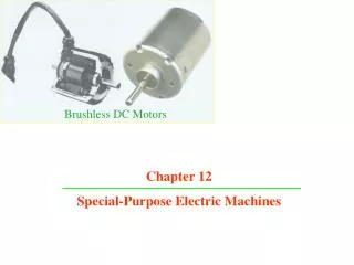
DC Machine Construction Figure 8.1 General arrangement of a dc machine
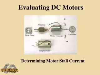
DC Machines • The stator of the dc motor has poles, which are excited by dc current to produce magnetic fields. • In the neutral zone, in the middle between the poles, commutating poles are placed to reduce sparking of the commutator. The commutating poles are supplied by dc current. • Compensating windings are mounted on the main poles. These short-circuited windings damp rotor oscillations. .
DC Machines • The poles are mounted on an iron core that provides a closed magnetic circuit. • The motor housing supports the iron core, the brushes and the bearings. • The rotor has a ring-shaped laminated iron core with slots. • Coils with several turns are placed in the slots. The distance between the two legs of the coil is about 180 electric degrees.
DC Machines • The coils are connected in series through the commutator segments. • The ends of each coil are connected to a commutator segment. • The commutator consists of insulated copper segments mounted on an insulated tube. • Two brushes are pressed to the commutator to permit current flow. • The brushes are placed in the neutral zone, where the magnetic field is close to zero, to reduce arcing.
DC Machines • The rotor has a ring-shaped laminated iron core with slots. • The commutator consists of insulated copper segments mounted on an insulated tube. • Two brushes are pressed to the commutator to permit current flow. • The brushes are placed in the neutral zone, where the magnetic field is close to zero, to reduce arcing.
DC Machines • The commutator switches the current from one rotor coil to the adjacent coil, • The switching requires the interruption of the coil current. • The sudden interruption of an inductive current generates high voltages . • The high voltage produces flashover and arcing between the commutator segment and the brush.
DC Machine Construction Figure 8.2 Commutator with the rotor coils connections.
DC Machine Construction Figure 8.3 Details of the commutator of a dc motor.
DC Machine Construction Figure 8.4 DC motor stator with poles visible.
DC Machine Construction Figure 8.5 Rotor of a dc motor.
DC Machine Construction Figure 8.6 Cutaway view of a dc motor.
DC Motor Operation • In a dc motor, the stator poles are supplied by dc excitation current, which produces a dc magnetic field. • The rotor is supplied by dc current through the brushes, commutator and coils. • The interaction of the magnetic field and rotor current generates a force that drives the motor
DC Motor Operation • The magnetic field lines enter into the rotor from the north pole (N) and exit toward the south pole (S). • The poles generate a magnetic field that is perpendicular to the current carrying conductors. • The interaction between the field and the current produces a Lorentz force, • The force is perpendicular to both the magnetic field and conductor (a) Rotor current flow from segment 1 to 2 (slot a to b) (b) Rotor current flow from segment 2 to 1 (slot b to a)
DC Motor Operation • The generated force turns the rotor until the coil reaches the neutral point between the poles. • At this point, the magnetic field becomes practically zero together with the force. • However, inertia drives the motor beyond the neutral zone where the direction of the magnetic field reverses. • To avoid the reversal of the force direction, the commutator changes the current direction, which maintains the counterclockwise rotation. . (a) Rotor current flow from segment 1 to 2 (slot a to b) (b) Rotor current flow from segment 2 to 1 (slot b to a)
DC Motor Operation • Before reaching the neutral zone, the current enters in segment 1 and exits from segment 2, • Therefore, current enters the coil end at slot a and exits from slot b during this stage. • After passing the neutral zone, the current enters segment 2 and exits from segment 1, • This reverses the current direction through the rotor coil, when the coil passes the neutral zone. • The result of this current reversal is the maintenance of the rotation. (a) Rotor current flow from segment 1 to 2 (slot a to b) (b) Rotor current flow from segment 2 to 1 (slot b to a)
DC Generator Operation • The N-S poles produce a dc magnetic field and the rotor coil turns in this field. • A turbine or other machine drives the rotor. • The conductors in the slots cut the magnetic flux lines, which induce voltage in the rotor coils. • The coil has two sides: one is placed in slot a, the other in slot b. (a) Rotor current flow from segment 1 to 2 (slot a to b) (b) Rotor current flow from segment 2 to 1 (slot b to a)
DC Generator Operation • In Figure 8.11A, the conductors in slot a are cutting the field lines entering into the rotor from the north pole, • The conductors in slot b are cutting the field lines exiting from the rotor to the south pole. • The cutting of the field lines generates voltage in the conductors. • The voltages generated in the two sides of the coil are added. (a) Rotor current flow from segment 1 to 2 (slot a to b) (b) Rotor current flow from segment 2 to 1 (slot b to a)
DC Generator Operation • The induced voltage is connected to the generator terminals through the commutator and brushes. • In Figure 8.11A, the induced voltage in b is positive, and in a is negative. • The positive terminal is connected to commutator segment 2 and to the conductors in slot b. • The negative terminal is connected to segment 1 and to the conductors in slot a. (a) Rotor current flow from segment 1 to 2 (slot a to b) (b) Rotor current flow from segment 2 to 1 (slot b to a)
DC Generator Operation • When the coil passes the neutral zone: • Conductors in slot a are then moving toward the south pole and cut flux lines exiting from the rotor • Conductors in slot b cut the flux lines entering the in slot b. • This changes the polarity of the induced voltage in the coil. • The voltage induced in a is now positive, and in b is negative. (a) Rotor current flow from segment 1 to 2 (slot a to b) (b) Rotor current flow from segment 2 to 1 (slot b to a)
DC Generator Operation • The simultaneously the commutator reverses its terminals, which assures that the output voltage (Vdc) polarity is unchanged. • In Figure 8.11B • the positive terminal is connected to commutator segment 1 and to the conductors in slot a. • The negative terminal is connected to segment 2 and to the conductors in slot b. (a) Rotor current flow from segment 1 to 2 (slot a to b) (b) Rotor current flow from segment 2 to 1 (slot b to a)
DC Generator Equivalent circuit • The magnetic field produced by the stator poles induces a voltage in the rotor (or armature) coils when the generator is rotated. • This induced voltage is represented by a voltage source. • The stator coil has resistance, which is connected in series. • The pole flux is produced by the DC excitation/field current, which is magnetically coupled to the rotor • The field circuit has resistance and a source • The voltage drop on the brushes represented by a battery
DC Generator Equivalent circuit • Figure 8.12 Equivalent circuit of a separately excited dc generator.
DC Generator Equivalent circuit • The magnetic field produced by the stator poles induces a voltage in the rotor (or armature) coils when the generator is rotated. • The dc field current of the poles generates a magnetic flux • The flux is proportional with the field current if the iron core is not saturated:
DC Generator Equivalent circuit • The rotor conductors cut the field lines that generate voltage in the coils. • The motor speed and flux equations are :
DC Generator Equivalent circuit • The combination of the three equation results the induced voltage equation: • The equation is simplified.
DC Generator Equivalent circuit • When the generator is loaded, the load current produces a voltage drop on the rotor winding resistance. • In addition, there is a more or less constant 1–3 V voltage drop on the brushes. • These two voltage drops reduce the terminal voltage of the generator. The terminal voltage is;
DC Motor Equivalent circuit • Figure 8.13 Equivalent circuit of a separately excited dc motor • Equivalent circuit is similar to the generator only the current directions are different
DC Motor Equivalent circuit • The operation equations are: • Armature voltage equation The induced voltage and motor speed vs angular frequency
DC Motor Equivalent circuit • The operation equations are: • The combination of the equations results in The current is calculated from this equation. The output power and torque are:
DC Motor Operation • There are four different methods for supplying the dc current to the motor or generator poles: • Separate excitation; • Shunt connection • Series connection • Compound
DC Motor Equivalent circuit • Figure 8.14 Equivalent circuit of a shunt dc motor
DC Motor Equivalent circuit • Figure 8.15 Equivalent circuit of a series dc motor
DC Motor Equivalent circuit • Figure 8.16 Equivalent circuit of a compound dc motor