Spread Spectrum
300 likes | 483 Views
Learn about the concepts and models of spread spectrum systems, including frequency hopping and direct sequence techniques. Discover how spread spectrum technology enhances data security and improves resistance to interference and jamming.

Spread Spectrum
E N D
Presentation Transcript
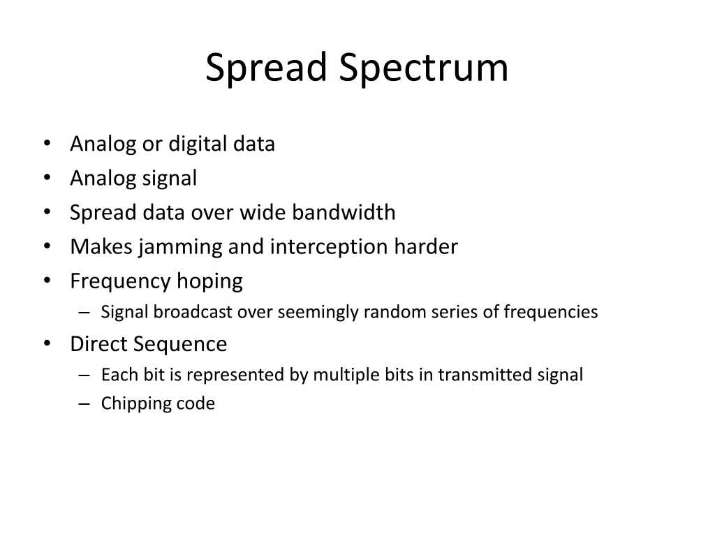
Spread Spectrum • Analog or digital data • Analog signal • Spread data over wide bandwidth • Makes jamming and interception harder • Frequency hoping • Signal broadcast over seemingly random series of frequencies • Direct Sequence • Each bit is represented by multiple bits in transmitted signal • Chipping code
Spread Spectrum Concept • Input fed into channel encoder • Produces narrow bandwidth analog signal around central frequency • Signal modulated using sequence of digits • Spreading code/sequence • Typically generated by pseudonoise/pseudorandom number generator • Increases bandwidth significantly • Spreads spectrum • Receiver uses same sequence to demodulate signal • Demodulated signal fed into channel decoder
Gains • Immunity from various noise and multipath distortion • Including jamming • Can hide/encrypt signals • Only receiver who knows spreading code can retrieve signal • Several users can share same higher bandwidth with little interference • Cellular telephones • Code division multiplexing (CDM) • Code division multiple access (CDMA)
Pseudorandom Numbers • Generated by algorithm using initial seed • Deterministic algorithm • Not actually random • If algorithm good, results pass reasonable tests of randomness • Need to know algorithm and seed to predict sequence
Frequency Hopping Spread Spectrum (FHSS) • Signal broadcast over seemingly random series of frequencies • Receiver hops between frequencies in sync with transmitter • Eavesdroppers hear unintelligible blips • Jamming on one frequency affects only a few bits
Basic Operation • Typically 2k carriers frequencies forming 2k channels • Channel spacing corresponds with bandwidth of input • Each channel used for fixed interval • 300 ms in IEEE 802.11 • Some number of bits transmitted using some encoding scheme • May be fractions of bit (see later) • Sequence dictated by spreading code
Slow and Fast FHSS • Frequency shifted every Tc seconds • Duration of signal element is Ts seconds • Slow FHSS has Tc Ts • Fast FHSS has Tc < Ts • Generally fast FHSS gives improved performance in noise (or jamming)
FHSS Performance Considerations • Typically large number of frequencies used • Improved resistance to jamming
Direct Sequence Spread Spectrum (DSSS) • Each bit represented by multiple bits using spreading code • Spreading code spreads signal across wider frequency band • In proportion to number of bits used • 10 bit spreading code spreads signal across 10 times bandwidth of 1 bit code • One method: • Combine input with spreading code using XOR • Input bit 1 inverts spreading code bit • Input zero bit doesn’t alter spreading code bit • Data rate equal to original spreading code • Performance similar to FHSS
Bit rate • Baud rate • Goal in data communication is to increase the bit rate while decreasing the baud rate. Increasing the data rate increases the speed of transmission, decreasing the baud rate decreases the bandwidth requirement.
Figure 5-1 Different Conversion Schemes
Figure 5-2 Digital to Digital Encoding
Figure 5-3 Types of Digital to Digital Encoding
Figure 5-4 Unipolar Encoding
Figure 5-5 Types of Polar Encoding
Polar schemes • The voltages are on both side of the time axis. • NRZ (non return to zero) • NRZ-L : The level of the voltage determines the value of bit. • NRZ-I : the change in the level of the voltage determines the level of the bit. If there is no change, the bit is 0, if there is a change, the bit is 1.
Figure 5-6 NRZ-L and NRZ-I Encoding
Figure 5-7 RZ Encoding
Return to zero • It uses three values: positive, negative and zero. • The signal changes not between bits but during the bit. The signal goes to zero in the middle of each bit. • The main disadvantage is that it requires two signal changes to encode a bit and therefore occupies greater bandwidth. • Another problem is its complexity.
Figure 5-8 Manchester and Diff. Manchester Encoding
Manchester encoding : the duration of bits is divided into two halves. The voltage remains at one level during the first half and moves to the other level in the second bit. • A negative to positive transition represents binary 1 and a positive to negative transition represents binary 0.