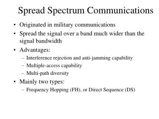
Spread Spectrum System
Explore the history and technology of spread spectrum systems for military RF communications, including its benefits, challenges, and applications in modern warfare. Learn about the innovative solutions and techniques used to enhance security and reliability.

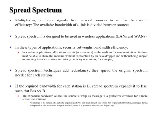
Spread Spectrum System
E N D
Presentation Transcript
90.9 WETA Military RF considerations • High-power, fixed-frequency transmitters make easy targets. • Easy to jam • Easy to destroy AGM-88High-speed Anti-Radiation (HARM) missile Missile seeker head locks on to RF transmitters
Spread Spectrum • This dilemma was recognized prior to WWII. • In 1942, Hedy Lamarr and pianist George Antheil patented a “Secret Communication System”. • Their scheme was for a frequency hoppingremote control for torpedo guidance.
First spread-spectrum patent • By changing the transmitter frequencies in a “random” pattern, the torpedo control signal could not be jammed. • Lamarr proposed using 88 frequencies sequencedfor control. Frequency switching pattern
R(t) t -> -1/n nTc Tc -nTc PN Sequence Generation • Codes are periodic and generated by a shift register and XOR • Maximum-length (ML) shift register sequences, m-stage shift register, length: n = 2m – 1 bits Output +
Generating PN Sequences • Take m=2 =>L=3 • cn=[1,1,0,1,1,0, . . .], usually written as bipolar cn=[1,1,-1,1,1,-1, . . .] Output +
Problems with m-sequences • Cross-correlations with other m-sequences generated by different input sequences can be quite high • Easy to guess connection setup in 2m samples so not too secure • In practice, Gold codes or Kasami sequences which combine the output of m-sequences are used.
Orthogonal Codes • Orthogonal codes • All pairwise cross correlations are zero • Fixed- and variable-length codes used in CDMA Systems • For CDMA application, each mobile user uses one sequence in the set as a spreading code • Provides zero cross correlation among all users
Introduction to Spread Spectrum • Problems such as capacity limits, propagation effects, synchronization occur with wireless systems • Spread spectrum modulation spreads out the modulated signal bandwidth so it is much greater than the message bandwidth • Independent code spreads signal at transmitter and despreads signal at receiver
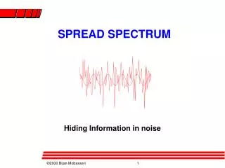
Spread Spectrum Technology • Problem of radio transmission: frequency dependent fading can wipe out narrow band signals for duration of the interference • Solution: spread the narrow band signal into a broad band signal using a special code interference spread signal signal power power spread interference detection at receiver f f
Spread Spectrum Technology • Side effects: • coexistence of several signals without dynamic coordination • tap-proof • Alternatives: Direct Sequence (DS/SS), Frequency Hopping (FH/SS) • Spread spectrum increases BW of message signal by a factor N, Processing Gain
Effects of spreading and interference user signal broadband interference narrowband interference P P i) ii) f f sender P P P iii) iv) v) f f f receiver
Spreading and frequency selective fading channelquality 2 1 5 6 narrowband channels 3 4 frequency Narrowband signal guard space channelquality 2 2 2 2 2 1 spread spectrum channels frequency spreadspectrum
Orthogonal Multiple Access • requires synchronization among the users, since the waveforms are orthogonal only if they are aligned in time. Walsh-Hadamard code To be polar, 0's are mapped to 1's and 1's are mapped to -1.
Orthogonal Multiple Access (3) • Disadvantage of Walsh-Hadamard code: • It have more than one autocorrelation peak , therefore need an external synchronization scheme. • Cross-correlation will affect it, so it is only used in synchronized CDMA • Spreading is not over the whole bandwidth, instead over a number of discrete frequency-component.
Non-orthogonal Multiple Access • Gold sequences are in particular popular for non-orthogonal CDMA. • By shifting one of the two PN sequence, we get a different Gold sequence. • Permits the transmission to be asynchronous. The receiver can synchronize using the auto-correlation property of the Gold sequence.
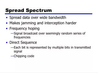
Spreading Spectrum Techniques • Direct Sequence (DS) • Frequency Hopping (FH) • Hybrid (DS/FH) • Time Hopping (TH) • Pulse FM System (Chirp)
DSSS (Direct Sequence Spread Spectrum) I • XOR the signal with pseudonoise (PN) sequence (chipping sequence) • Advantages • reduces frequency selective fading • in cellular networks • base stations can use the same frequency range • several base stations can detect and recover the signal • But, needs precise power control Tb user data 0 1 XOR Tc chipping sequence 0 1 1 0 1 0 1 0 1 1 0 1 0 1 = resulting signal 0 1 1 0 1 0 1 1 0 0 1 0 1 0
Processing Gain (spreading factor) Period of one data bit PG = SF = Tb / Tc Period of one chip
DSSS (Direct Sequence Spread Spectrum) II transmitter Spread spectrum Signal y(t)=m(t)c(t) transmit signal user data m(t) X modulator chipping sequence, c(t) radio carrier receiver correlator sampled sums products received signal data demodulator X integrator decision radio carrier Chipping sequence, c(t)
Direct Sequence SS Source: http://www.sss-mag.com/primer.html Source: http://murray.newcastle.edu.au/users/staff/eemf/ELEC351/SProjects/Morris/types.htm
DS/SS Comments • Secure and Jamming Resistant • Both receiver and transmitter must know c(t) • Since PSD is low, hard to tell if signal present • Since wide response, tough to jam everything • Multiple access • If ci(t) is orthogonal to cj(t), then users do not interfere • Near/Far problem • Users must be received with the same power
FH/SS (Frequency Hopping Spread Spectrum) I • Discrete changes of carrier frequency • sequence of frequency changes determined via PN sequence • Two versions • Fast Hopping: several frequencies per user bit (FFH) • Slow Hopping: several user bits per frequency (SFH) • Advantages • frequency selective fading and interference limited to short period • uses only small portion of spectrum at any time • Disadvantages • not as robust as DS/SS • simpler to detect
FHSS (Frequency Hopping Spread Spectrum) III narrowband signal Spread transmit signal transmitter user data modulator modulator hopping sequence frequency synthesizer receiver received signal data demodulator demodulator hopping sequence frequency synthesizer
Frequency Hopping SS Source: http://murray.newcastle.edu.au/users/staff/eemf/ELEC351/SProjects/Morris/types.htm
TIME HOPPING SYSTEMS • A time hopping system is a spread spectrum system in which the period and duty cycle of a pulsed RF carrier are varied in a pseudorandom manner under the control of a coded sequence • Time hopped spread spectrum systems have found no commercial application to date. However, the arrival of cheap random access memory (RAM) and fast micro-controller chips make time hopping a viable alternative spread spectrum technique for the future. • Time hopping is a system in which burst signal are initiated at pseudo random rate. In this the transmitter is switched ON and OFF by a code sequence. The main difference between a frequency hopping and time hopping system is that in the former the transmitted frequency changes at each code chip time in the later the frequency changes occurs only at zero/ one transitions in the code sequence.
Storage Device Modulator S (t) Time slot Activator PN code Generator Clock TRANSMISSION OF THSS
On-off switches Demodulator PN code Generator Bit timing Clock VCO Storage THSS RECEIVER
THSS (contd) • Advantages • Has a high bandwidth efficiency as compared to FH and DSSS. • Its implementation is simpler than that of FHSS • Near-far problem can be avoided in a coordinated system • Disadvantages • Has a very long acquisition time. • Also requires error correction
PN Synchronization • Synchronization uncertainty • Time uncertainty • Distance between Tx-Rx (propagation delay) • Relative clock shifts • Different phase between Tx-Rx (carrier, PN sequence) • Frequency uncertainty • Two steps: • Acquisition (coarse alignment) • Tracking (fine alignment)
Acquisition Phase • Received signal and the locally generated PN sequence are correlated with a coarse time step to produce a measure of similarity between the two.
Acquisition Phase (2) • If not exceeded, sequence is advanced by Tc/2 and repeat correlation process.
Applications of Spread Spectrum • Cell phones • IS-95 (DS/SS) • GSM • Global Positioning System (GPS) • Wireless LANs • 802.11b
Performance of DS/SS Systems • Pseudonoise (PN) codes • Spread signal at the transmitter • Despread signal at the receiver • Ideal PN sequences should be • Orthogonal (no interference) • Random (security) • Autocorrelation similar to white noise (high at t=0 and low for t not equal 0)
Detecting DS/SS PSK Signals transmitter Spread spectrum Signal y(t)=m(t)c(t) transmit signal Bipolar, NRZ m(t) X X PN sequence, c(t) sqrt(2)cos(wct + q) receiver received signal z(t) w(t) data decision integrator LPF X X x(t) c(t) sqrt(2)cos(wct + q)
Optimum Detection of DS/SS PSK • Recall, bipolar signaling (PSK) and white noise give the optimum error probability • Not effected by spreading • Wideband noise not affected by spreading • Narrowband noise reduced by spreading
Tb Tc Signal Spectra • Effective noise power is channel noise power plus jamming (NB) signal power divided by N
Multiple Access Performance • Assume K users in the same frequency band, • Interested in user 1, other users interfere 4 6 5 1 3 2
Code Division Multiple Access (CDMA) • Multiplexing Technique used with spread spectrum • Start with data signal rate D • Called bit data rate • Break each bit into k chips according to fixed pattern specific to each user • User’s code • New channel has chip data rate kD chips per second • E.g. k=6, three users (A,B,C) communicating with base receiver R • Code for A = <1,-1,-1,1,-1,1> • Code for B = <1,1,-1,-1,1,1> • Code for C = <1,1,-1,1,1,-1>
CDMA Explanation • Consider A communicating with base • Base knows A’s code • Assume communication already synchronized • A wants to send a 1 • Send chip pattern <1,-1,-1,1,-1,1> • A’s code • A wants to send 0 • Send chip[ pattern <-1,1,1,-1,1,-1> • Complement of A’s code • Decoder ignores other sources when using A’s code to decode • Orthogonal codes