Bulk Deformation Processes in Metalworking
550 likes | 1.21k Views
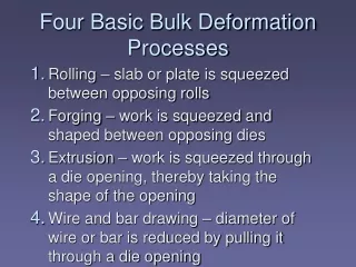
Bulk Deformation Processes in Metalworking. Rolling. Rolling - deformation process with thickness reduced by compressive forces exerted by two opposing rolls. Rolling Analysis. Conservation of material Continuity of volume flow rate Forward slip Rolling force, F. Rolling Analysis.

Bulk Deformation Processes in Metalworking
E N D
Presentation Transcript
Rolling Rolling - deformation process with thickness reduced by compressive forces exerted by two opposing rolls.
Rolling Analysis Conservation of material Continuity of volume flow rate Forward slip Rolling force, F
Rolling Analysis Where the deformation strain and the average flow stress The torque required for the deformation process The power required by the process is
Rolling Mechanics The rolling process is governed by the frictional force between the rollers and the workpiece. The frictional force at the entrance side is higher than that at the exit side. This allows the roller to pull the workpiece towards the exit end.
Friction vo<vr<vf Maximum draft, which is the thickness reduction, is given as 2R. Coefficient of friction depends on lubrication, typically: cold working 0.1 warm working 0.2 hot working 0.4
Material and Process Parameters Material Parameters • ductility • coefficient of friction • strength, modulus and Poisson’s ratio Process Parameters • roller speed • power • draft • lubrication
Shape Rolling In addition to the material and process parameters, the rollers will acts as a set of dies and have to be pre-formed to take the negative shape of the cross-section. There may be more than one set of rollers required to reduce the workpiece to the appropriate shape.
Rolling Mill Configurations a) two high b) three high c) four high d) cluster mill e) tandem rolling mill
Ring Rolling • To make a larger and thinner ring from the original ring • Usually a hot rolling process for large rings and cold rolling for small rings • Typical applications: bearing races, steel tires, rings for pressure vessel.
Thread Rolling • Production of external thread • Cold rolling • High and competitive production rate (up to 8 parts per second)
Gear Rolling • Similar to the screw thread. • Typically for helical gears • Shares the same advantages: • better material usage • smoother surface • stronger thread due to work hardening • better fatigue resistance due to compression
Roll Piercing • Hot working process • Production of Seamless thick-wall tubes
Forging Open-die forging Flashless forging Impression-die forging
Mechanics of Forging Under ideal condition: Where F = forging force Yf= flow stress A = cross-section of part
Forging In open-die forging, barreling occurs. But with hot forging, the issue is complicated by the thermal distribution within the workpiece and the associated flow of metal.
Shape factor The actual forging force is greater than the ideal case. The shape factor is to cover the effect of barreling and the friction effect. Open-die forging is not a net-shape process and will require subsequent machining to dimension. Load-stroke curve
Open-die Forging Fullering Edging Cogging
Open-die Forging • Fullering Reducing workpiece cross section to prepare for subsequent shaping action. Dies with convex surface cavity are used. • Edging Similar to Fullering, but the dies have concave surface cavitiy. • Cogging Open dies with flat or slightly contoured surfaces to reduce cross-section and to increase length.
Impression-die Forging Dies containing the inverse of the shape of the part. Flash is allowed on the parting surface. The flash serves as a constraint for metal flow in the die and help to fill the intricate details of the cavity. Higher forging forces are required in this process than open-die forging. The shape factor generally will have a higher value.
Impression-die Forging • The forces are largest at the end of the process when the projected area of the blank and the friction is largest. • Again, progressive dies are needed to transform the starting blank into a final desired geometry. • Machining is needed to produce the fine tolerance needed.
Impression-die Forging Pros: • high production rate • conservation of metal • greater strength • favorable grain orientation Forging Machining
Flashless Forging Conventional forging part Precision forging part
Flashless Forging The volume control is important and the outcome is precision re-production of inverse of cavity geometry. Typically for aluminum and magnesium alloy.
Drop Hammer and Dies Dies are normally made from tool steel with high impact strength and high wear resistance. Webs - Thin section parallel to parting line. Ribs - thin section perpendicular to parting line Gutter - area for containing flash
Upsetting and Heading Upsetting and Heading The leading section of the stock is forged to form a head section using closed-die forging.
Upsetting and Heading Upsetting is used to form heads of screw and bolt with different geometric forms.
Swaging Swaging used to reduce the cross-sections of forged rods or tubes using a set of rotating dies. A mandrel is sometimes used to control the internal form of the tube. Radial forging rotates the stock rather than the die.
Orbital Forging Small contact area reduce the forging force required substantially.
Hobbing To press the die against the softer blank to form the final shape.
Trimming Trimming is a shearing process to remove the flash from the workpiece.
Design Considerations • Material • Die design • Machine • Machine processing range • Machine process setting
Design Considerations Material • Ductility • Strength • Plastic deformation law (constitutive relationship) • Coefficient (Die/workpiece) • Variation of properties at processing temperature range
Design Considerations Die Design • Number of die stations (progressive die) • Geometric complexity of the part • Die geometric details • Draft angle, fillet, radii • Webs and ribs • Flash • Parting surface and parting direction • Die material • Die life
Design Considerations Machine processing range • Maximum forging force • Maximum power • Maximum speed • Maximum die size
Design Considerations Machine process setting • No. of stations • Velocity profile • Temperature / time profile • Force