Download
1 / 13
130 likes | 301 Views
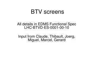
The TV Beam Observation system - BTV. TV Beam observation systems (BTV) are used to monitor the transverse shape of the beam during commissioning and setup.

E N D
The TV Beam Observation system - BTV • TV Beam observation systems (BTV) are used to monitor the transverse shape of the beam during commissioning and setup. • The main use consists in intercepting the beam on a single passage. In the injection/extraction transfer lines this is so by definition. In the ring this is obtained by stopping the beam before it completes one turn, in the case of LHC this must be obtained by dumping the beam. • A special use of the BTV systems is for optics matching studies, where beam size oscillations are observed over a certain number of turns. In this case the beam must be allowed to circulate for a predefined number of turns and then dumped otherwise the radiator can be damaged. • The BTVs consist of a vacuum tank containing a moveable radiator and an observation view port, an observation camera, a set of remote controlled optical filters to adapt the light intensity and an electronic chain to control the system and acquire the images. • The control electronics consists of a custom VME board plus some electronics box in the tunnel for the transmission of the signals (up to 1 km)
Inventory of the BTV system • Screens in the injection system (single turn) (per beam) • 9 screens in the transfer lines BTVI • one screen just after the septum BTVSS • one screen before the kickers BTVSI • one screen after the kickers BTVSI • one screen before the TDI BTVST • Screens in the LHC ring • 1 screen for observation of first turn (single turn) BTVSI • 4 screens for observation of first turn (single turn) or matching (few turns) BTVM (BTVSI) • Screens in the beam dump lines (single turn) (per beam) • one screen at the entrance of the line BTVSE • one screen downstream of the dilution kickers BTVD • one screen in front of the beam dump block (always IN)BTVDD http://ab-dep-bi-pm.web.cern.ch/ab-dep-bi-pm/?n=Activities.BTVLHC
BTVs in the injection regions (IR2 and IR8) TI BTVI BTVSS BTVSI BTVSI BTVST Septum Kicker D2 TDI D1 20mm 30mm Illustration drawing only: septum magnet deflects in H-plane, kicker magnet deflects in V-plane • Each BTV is equipped with two screens: a Titanium OTR foil and an Alumina (Chromox) screen
BTV screens and machine protection • First priority is to prevent damage to LHC machine components due to the interaction of a screen or its support with the beam. For this reason all interlocks are implemented in hardware. • Second priority is to prevent damage to screens. In this case interlocks can be implemented in software. Protection principles • All screens that could possibly interact with the circulating beams in the LHC are only permitted to be IN or MOVING, when the SafeBeamFlag==TRUE (at 450GeV this corresponds to about 1012 protons) • If SafeBeamFlag==FALSE, and the screen moves away from the end switch indicating the OUT position a beam dump is generated via the BIC. • The first two screens in the Beam Dump Lines (BTVSE and BTVD) can only be IN or MOVING when SafeBeamFlag==TRUE (as the other screens in the ring) The Ring screens can never be IN when SafeBeamFlag==FALSE
Screens on the circulating beam Screen: Ti 12 m Intensity: 1 x 1.1E11 Transverse size: x,y= 0.9 mm Screen: Ti 12 m Intensity: 1 x 5.5E10 Transverse size: x,y= 0.9 mm
Screens for injection • A circulating beam with intensity above 1011 protons circulating for more than a few seconds will damage the Titanium screens • For alumina this limit is much lower In the case we need to operate with intensities above this limit • Screens for matching need to be IN for several turns, then the beam must be extracted (otherwise damage of the screen) • Screens for injection need to be IN for one turn, the beam must be extracted (otherwise damage of the screen) Options for interlocking • When using screens, limit the intensity to below 2∙1010. Could be done limiting the intensity in the SPS by using a high resolution BCT • Use BLM close to screen. If Signal>threshold, dump beam • Interlocking the screen and dumping the beam automatically after a short time
BTV screens Interlock logic BTV Maskable BIC Input Logic Implemented in the BTV system
BTV screens Interlock logic cont’d Unmaskable BIC input (turn limit) Turn clock Injection Kicker Magnet trigger BIC unmaskable input Delay Screens in 3, 4 and 7: (SW signal) TRUE if BTV = IN AND Injection region screens: (HW signal) TRUE if BTV = IN Maskable BIC input (Current limit) BIC maskable input All BTVs: HW signal if BTV SAFE see previous slide for the meaning of SAFE Safe Beam Flag
BTV tests in TT40 / TT41 (J.Wenninger) In order for the Interlock system to be useful it must be operational and failures must be easy to detect • A procedure for the commissioning of the interlock system has been established and tested on the CNGS line TT40 / TT41 in 2005 (without beam): • The test procedures were prepared • The interlock tests were performed • The outcome of the tests was documented • After a few iteration the system behaved as expected https://webh06.cern.ch/sps-mp-operation/
Alignment mirrors for synchrotron light observation • Mirrors must always be OUT when operating with beam • The Interlock of the alignment mirrors will use an available input on the BTV system • IF MIRROR OUT then UserPermit = FALSE • Will block beam operation, if UserPermit for BTV is not masked • Will always block operation with beam intensity above 1012 protons (also if UserPermit for BTVs is masked) • Should be also interlocked by software (possibly in the injection sequencer)
Considerations on the speed of BTV screens and beam losses • Assume a speed of the mechanism of 1 mm / 20 ms (50 mm/s) • Assume a beam size of = 0.2 mm (for 7 TeV) • The time to advance the screen by one is 4 ms • Detection of beam losses and dumping the beam by beam loss monitors: • should not take longer than 0.4 ms, during this time the screen advances by 0.1 (normally, it should take only 0.3 ms) • ...even if it takes 1 ms, the screen advances by 0.25 • Assuming a beam with nominal intensity that is cut at n .... the number of protons that will hit the screen is: • moving from 5 to 4.75 : 4.6 E+8 • moving from 4 to 3.75 : 3.3 E+11 • moving from 3 to 2.75 : 6.9 E+12 To be confirmed: calculate the response of beam loss monitors in this case, and show that BLMs can detect such losses
Comments and outlook • The possibility of increasing the reliability of the position switches on the BTV systems by adding redundancy is being verified • Already now in order for a BTV to declare the screen OUT the OUT limit switch must to be pressed. In case of failure of the switch it is very unlikely that it will be jammed in the closed position (never observed before) • The possibility of reducing the speed of the screens is also under investigation • A different type of motors (higher speed reduction factor) has already been ordered and will be tested soon, if needed the BTV systems can be modified using this type of motors.