Download
1 / 16
160 likes | 264 Views
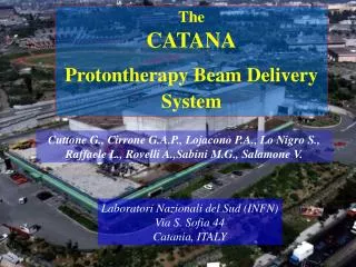
The CATANA Protontherapy Beam Delivery System. Cuttone G., Cirrone G.A.P., Lojacono P.A., Lo Nigro S., Raffaele L., Rovelli A.,Sabini M.G., Salamone V. Laboratori Nazionali del Sud (INFN) Via S. Sofia 44 Catania, ITALY.

E N D
The CATANA Protontherapy Beam Delivery System Cuttone G., Cirrone G.A.P., Lojacono P.A., Lo Nigro S., Raffaele L., Rovelli A.,Sabini M.G., Salamone V. Laboratori Nazionali del Sud (INFN) Via S. Sofia 44 Catania, ITALY
LNS Superconducting Cyclotron is the unique machine in in Italy and South Europe used for protontherapy Treatment of the choroidal melanoma In Italy about 300 new cases for year
PRESENT TREATMENT ROOM • 0 ° respect the switching magnet • 80 meter after extraction • 3 m proton beam line LAYOUT OF LNS
WITH A BARE BUT VERY STABLE TABLE AND A SUPERCONDUCTOR CYCLOTRON SUITABLE FOR62 AMeV PROTON BEAM 1999 OUR HISTORY STARTED THREE YEARS AGO......
FIRST OF ALL WE TOOK IN CONSIDERATION TWO PARAMETER FOR THE DEVELOPMENT OF OUR PROTON BEAM DELIVERY SYSTEM: In order to obtain ranges up to 30 mm E.T. at isocenter in air • ENERGY In order to reach a proton beam irradiation field: In terms of lateral dose distribution in air • OMOGENEITY • At least 30 mm in diameter • Omogeneus within 2.5 % • With lateral penumbra of about 1mm
SIMULATION TOOLKIT : TRIM2000 UNDER NT OS GEANT3.0 UNDER LINUX RED HAT 6.1 OS SINGLE SCATTERER FOIL 300 m Tantalum DOUBLE SCATTERER FOIL 80 m + 20 m Tantalum DOUBLE SCATTERER FOIL WITH CENTRAL STOPPER 15 m + 25 m + 7 mm thick copper beam stopper WE DECIDED FOR A PASSIVE SCATTERER SYSTEM AND STUDIED THREE DIFFERENT EXPERIMENTAL CONFIGUARATIONS
EXPERIMENTAL RESULTS OUR BEAM PROFILE WITH A 50 mm DIAMETER FINAL COLLIMATOR SIMULATION VS. EXPERIMENTAL RESULT
EXPERIMENTAL RESULTS LNS PURE BRAGG PEAK
Modulator & Range shifter Ligth field Scatterer system Monitor chambers Laser
JUST AFTER THE FIRST SCATTERER WE EVALUATED THE PROTON BEAM LATERAL DISTRIBUTION ALONG OUR BEAM LINE
IN COLLABORATION WITH CCO WE PRODUCED A PRELIMINARY SET OF MODULATORS It is interesting to note we didn’t find any difference in the experimental results, varing this distance from 15 cm up to 33 cm The actual distance beetwen modulator and range shifter is 33 cm
ACTUALLY THE BEAM LINE IS READY 1999 2002, February
WE ACKNOWLEDGE FOR THEIR SUPPORT AND ENCOURAGEMENT: CCO A. Kacperek M. Sheen PSI E. Egger TRIUMF E. Blackmore MGH B. Gottshalk AND LAST BUT NOT AT LEAST Prof. G. Biti University of Florence For his support in clinical authorization