Download
1 / 17
170 likes | 336 Views
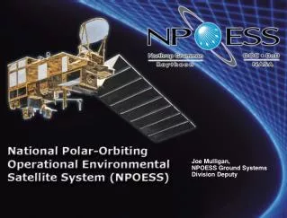
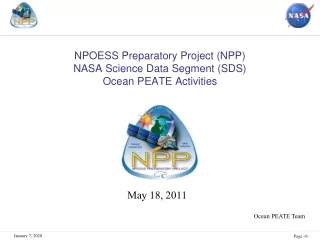
National Polar-orbiting Operational Environmental Satellite System (NPOESS). An Introduction to NPOESS. May 19, 2003. Joseph E. Mulligan NPOESS Interface Data Processing Segment Lead. A Tri-agency Effort to Leverage and Combine Environmental Satellite Activities. NPOESS. NPOESS. Mission

E N D
National Polar-orbiting Operational Environmental Satellite System (NPOESS) An Introduction to NPOESS May 19, 2003 Joseph E. Mulligan NPOESS Interface Data Processing Segment Lead
A Tri-agency Effort to Leverage and Combine Environmental Satellite Activities NPOESS NPOESS Mission Provide a national, operational, polar remote-sensing capability Achieve National Performance Review (NPR) savings by converging DoD and NOAA satellite programs Incorporate new technologies from NASA Encourage International Cooperation METOP 0530 1330 0930 Local Equatorial Crossing Time NPOESS Saves as much as $1.3B from the cost of previously planned separate developments
NPOESS Overview • Contract was awarded on August 23, 2002 to Northrop Grumman Space Technology • Contract consists of: • 6 satellites • Taking over all government instrument contracts • Buying all “leveraged” instruments • Integrating GFE instruments (ADCS and SARSAT) • Building and deploying all ground systems • C3 and data retrieval • Data processing hardware and software • Software for worldwide users • Operating system through IOC (2011) • with option to 2018
NPOESS Overview METOP DMSP 0830 1330 0930 0530 POES Local Equatorial Crossing Time DMSP Tomorrow (2005) • 4-Orbit System • 2 US Military • 1 US Civilian • 1 EUMETSAT/METOP U.S. civil and defense programs, working in partnership with EUMETSAT, will ensure improved global coverage and long-term continuity of observations at less cost! METOP POES NPOESS DMSP NPOESS 0730 0530 1330 1330 0930 0830 0530 POES SpecializedSatellites LocalEquatorialCrossingTime Local Equatorial Crossing Time DMSP NPOESS Future (2008-2018) • 3-Orbit System • 3 US Converged • 1 EUMETSAT/METOP • Specialized Satellites • Today • 4-Orbit System • 2 US Military • 2 US Civilian
Satellite Transition Schedule CY 99 00 01 02 03 04 05 06 07 08 09 10 11 12 13 14 15 16 17 18 ----------------10 Year Mission Life------------------- 0530 F17 F19 F20 C3 C6 NPOESS DMSP WindSat/Coriolis F15 F16 C4 F18 C1 NPOESS DMSP NPOESS 0730 - 1030 17 POES METOP EOS-Terra Local Equatorial Crossing Time NPP C5 NPOESS POES 1330 N 16 C2 N’ Earliest Need to back-up launch EOS-Aqua Mission Satisfaction S/C Deliveries Earliest Availability FY 99 00 01 02 03 04 05 06 07 08 09 10 11 12 13 14 15 16 17 18 S/C delivery interval driven by 15 month IAT schedule As of: 20 Oct 02 Most probable launch date Launch date based on backup need
NPOESS Top Level Architecture GPS SpaceSegment NPP(1030) NPOESS1330 NPOESS1730 NPOESS2130 Low Rate Data/High Rate Data(LRD/HRD) Command& ControlSegment NPP Science Data Segment Field Terminal Segment Svalbard CLASS ADS 15 Globally DistributedReceptor Sites FNMOC NAVOCEANO AFWA NESDIS/NCEP Alternate MMCat Schriever AFB Mission ManagementCenter (MMC)at Suitland Interface Data Processing Segment NOAA Comprehensive Large Array Data Stewardship System NPP Data & Control Flow NPOESS Data & Control Flow ADS CLASS NPP Archive & Distribution Seg 128 attributes above, 724 at, 9 below threshold • Data Quality • SMD/HRD • LRD 305 attributes above, 180 at, 0 below threshold Threshold Objective • Data Latency • SMD • HRD/LRD Data Availability Operational Availability
CMIS - μwave imager VIIRS - vis/IR imager CrIS - IR sounder ATMS - μwave sounder OMPS - ozone GPSOS - GPS occultation ADCS - data collection SESS - space environment APS - aerosol polarimeter SARSAT - search & rescue TSIS - solar irradiance ERBS - Earth radiation budget ALT - altimeter 1330 1730 2130 VIIRS X X X CMIS X X X CrIS X X ATMS X X SESS X GPSOS X OMPS X ADCS X X SARSAT X X X ERBS X SS X X X ALT X TSIS X NPOESS Satellite CMIS ATMS CrIS VIIRS OMPS ERBS NPOESS 1330 Configuration Single satellite design with common sensor locations
Visible/Infrared Imager Radiometer Suite (VIIRS) Raytheon Santa Barbara Research Center 0.4 km imaging and 0.8 km radiometer resolution 22 spectral bands covering 0.4 to 12.5 mm Automatic dual VNIR and triple DNB gains Spectrally and radiometrically calibrated EDR-dependent swath widths of 1700, 2000, and 3000 km Cross-track Infrared Sounder (CrIS) ITT Fort Wayne 158 SWIR (3.92 to 4.64 mm) channels 432 MWIR (5.71 to 8.26 mm) channels 711 LWIR (9.14 to 15.38 mm) channels 3x3 detector array with 15 km ground center-to-center 2200 km swath width Conical Scanning Microwave Imager/Sounder (CMIS) Boeing Space Systems 2.2 m antenna RF imaging at 6, 10, 18, 36, 90, and 166 GHz Profiling at 23, 50 to 60, 183 GHz Polarimetry at 10, 18, 36 GHz 1700 km swath width Development Sensor Highlights
Development Sensor Highlights (cont.) • Advanced Technology Microwave Sounder (ATMS) Northrop Grumman Electronics • CrIS companion cross track scan • Profiling at 23, 50 to 57, 183 GHz • Surface measurements at 31.4, 88, 165 GHz • 1.1, 3.3, and 5.2 deg (SDRs resampled) • 2300 km swath width • Ozone Mapping and Profiler Suite (OMPS) Ball Brothers • Total ozone column 300 to 380 nm with 1.0 nm resolution • Nadir ozone profile 250 to 310 nm with 1.0 nm resolution • Limb ozone profile 290 to 1000 nm with 2.4 to 54 nm resolution • Swath width of 2800 km for total column • Global Positioning System Occultation Sensor (GPSOS) Saab Erikson • RF receiver/processor of GPS signals at 1575.42 and 1227.60 MHz • Velocity, anti-velocity and nadir views
Leverage Sensor Highlights • Radar Altimeter (ALT) Alcotel • Measures range to ocean surface with a radar at 13.5 GHz • Corrects for ionosphere with 5.3 GHz radar • Corrects for atmosphere with CMIS water vapor measurements • Precise orbit determination with GPS • Earth’s Radiation Budget Suite (ERBS) Northrop Grumman Space Technology • Three spectral channels • Total radiation measurement 0.3 to 50 mm • Shortwave Vis and IR measurement 0.3 to 5 mm • Longwave IR measurement 8 to 12 mm • Total Solar Irradiance Sensor (TSIS) University of Colorado • Two sensors for total irradiance (TIM) and spectral irradiance (SIM) • TIM measures total solar irradiance • SIM measures spectral irradiance 200 to 2000 nm • Pointing platform and sensor suite to be provided by CU LASP
Highlights of Other Sensors • Space Environment Sensor Suite (SESS) • Sensor suite collecting data on particles, fields, aurora, and ionosphere • Suite includes a UV disk imager (BATC), EUV limb imager (BATC), charged particle detectors (Amptek/U. of Chicago), thermal plasma sensors (UTD), a magnetometer (MEDA), and a coherent beacon sensor (AIL) • Advanced Data Collection System (ADCS) and Search and Rescue Satellite-Aided Tracking (SARSAT) • “GFE” to NPOESS from France and Canada • ADCS supports global environmental applications • SARSAT collects distress beacon signals • Aerosol Polarimetry Sensor (APS) Raytheon Santa Barbara Research Center • Aerosol characterizations of size, single scattering albedo, aerosol refractive index, aerosol phase function • Multispectral (broad, 0.4 to 2.25 mm) • Multiangular (175 angles) • Polarization (all states)
NPOESS EDR-to-Sensor Mapping55 Product Sets [RDR, SDR, EDR] Cloud Top Pressure Cloud Top Temperature Downward Longwave Radiance (Sfc) Downward Shortwave Radiance(Sfc) Electric Field Electron Density Profile Energetic Ions Geomagnetic Field Ice Surface Temperature In-situ Plasma Fluctuations In-situ Plasma Temperature Ionospheric Scintillation Medium Energy Charged Particles Land Surface Temperature Net Heat Flux Net Solar Radiation (TOA) Neutral Density Profile Color/Chlorophyll Ocean Wave Characteristics Outgoing Longwave Radiation (TOA) Ozone - Total Column/Profile Precipitable Water Precipitation Type/Rate Pressure (Surface/Profile) Sea Ice Characterization Sea Surface Height/Topography Snow Cover/Depth Solar Irradiance Supra-Thermal-Auroral Particles Surface Type Wind Stress Suspended Matter Total Water Content Vegetation Index Atmospheric Vertical Moisture Profile Atmospheric Vertical Temp Profile Imagery Sea Surface Temperature Sea Surface Winds Soil Moisture Aerosol Optical Thickness Aerosol Particle Size Aerosol Refractive Index Albedo (Surface) Auroral Boundary Auroral Energy Deposition Auroral Imagery Cloud Base Height Cloud Cover/Layers Cloud Effective Particle Size Cloud Ice Water Path Cloud Liquid Water Cloud Optical Thickness Cloud Particle Size/Distribution Cloud Top Height VIIRS (23) CMIS (19) CrIS/ATMS (3) OMPS (1) SES (13) GPSOS (2) ERBS (5) TSIS (1) ALTIMETER (3) APS (4) Environmental Data Records (EDRs) with Key Performance Parameters
Receptor Sites SafetyNet -- 15 globally distributed SMD receptors linked to the centrals via commercial fiber -- enables low data latency and high data availability – 55% of the orbit has connectivity to one of the Safety Net nodes
NPOESS EDR Processing Timeline End-to-End EDR Latency 100% 90% 95% of data delivered within 28 min 80% 70% > 77% of data delivered within 15 min 60% Percent of EDR Products Delivered 50% 40% Average < 10.5 min 30% 20% Earliest Data Delivered < 2 min 10% 0% 0 5 10 15 20 25 30 35 40 45 50 Time from Observation to Delivery (minutes)
Interface Data Processing Segment • High performance computing hardware • Each Central has a complete system (IDP) that will generate all products within required latencies • Each IDPS or Central contains an Operations string, an Integration and Test (I&T) string, and shared disk arrays (RAID) • Operations string carries 100% reserve capacity and additional availability processors • I&T string can be used for integration and test of new software, support for technology insertion, parallel operations, failover, and algorithm development • Modular, workflow managed software • Receives multiple data streams from C3S, processes data into RDRs, SDRs, TDRs, and EDRs, packages products into form useful for Centrals, and delivers requested products to end users • Centrals have control over what products are created, which ancillary data sets are used, and how products are delivered • Highly automated, fault-tolerant design requires minimal staff • IDPS operator supported by System Administrator ensures proper operations • Cal/Val analyst monitors and validates IDPS products • Same software is used in field terminals • Will be made available worldwide via download from the internet
IDPS Data Delivery • Receives RDRs, TDRs, SDRs, and EDRs from Data Management subsystem • Aggregates and reformats into HDF 5 • Small granules necessary for processing are not seen by external users • Size and delivery frequency of products controlled by external users • Provides products to the Centrals, Cal/Val, ADS/CLASS, and SDS via a file transfer or common disk services
Policy and Planning • NPOESS will deliver data to users world-wide in accordance with US national data policy • Data will be broadcast openly around the world at no cost to receivers • Capability for data encryption/data denial exists for national defense needs • Denial can be done on a world-wide or geographic basis • NPOESS will provide certified data processing software via the Internet to anyone who wishes to use it