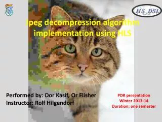
Jpeg decompression algorithm implementation using HLS
Jpeg decompression algorithm implementation using HLS. midterm presentation Winter 2013-14. Performed by: Dor Kasif, Or Flisher Instructor: Rolf Hilgendorf. JPEG - standard for compression of digital images. Done by software , takes a lot of system resources. The solution

Jpeg decompression algorithm implementation using HLS
E N D
Presentation Transcript
Jpeg decompression algorithm implementation using HLS midterm presentation Winter 2013-14 Performed by: Dor Kasif, Or FlisherInstructor: Rolf Hilgendorf
JPEG- standard for compression of digital images. Done by software, takes a lot of system resources. The solution Implementation of the JPEG decompression/compression algorithm on adedicated hardware. The Necessity
Design of hardware is done by Hardware Description Languages (HDL. VHDL etc…). HDL’s are programmed concurrently, and is problematic for complicated designs. Programming languages (C/C++,JAVA etc..) are easier to comprehend. The solution using HLS(High Level Synthesis), which enables the use of a programming language as the design and synthesis language. Implementation on hardware
Our objective Developing a decompressorin a programming language (C++), converting it to a Hardware Description Languages(VHDL) Using Vivado HLS, and Implementing it on a FPGA. The decompressed image will then be available for display on screen in RGBformat.
Project Goals • Implementing the Jpeg decompression algorithm on a FPGA Using HLS. • Displaying the decompressed image in a RGBformat on screen. • Optimize the implementation to reach the optimal performances possible within the performance envelope of the FPGA. • Compare the software decompressed picture to the hardware decompressed picture in terms of Structural Similarity Index Metric (SSIM) .
Dividing into 3 channels RGBformat is divided into 3 color channels,each with it’s own matrix sharing the same size (usually). The encoding /decoding algorithm is done for each channel separately.
The JPEG encoding algorithm. The decoding algorithm is done exactly the same, but in reverse!
Example picture- Lena Picture after encoding and decompressing Input picture
Block diagramHighest Hierarchy 27 bits Encoded picture JPEG Testbench (in C++) JPEG-DECOMPRESSOR Module (convert from C++ to VHDL using HLS) 8x8 decompressed block Hand shake protocol
Block diagramHighest Hierarchy • We use the test bench file ,which inputs the encoded image stream of bits into the module file aka the decoder. • The test bench is sending a stream of 27 bits to the module each time. • The maximum length of the AC/DC Huffman tables is 27 bits. • The module constructs a full sub matrix block of size 8x8. • The module will announce the completion of the 8x8 sub matrix through a handshake procedure. • The image will then be ready for display on screen in RGBformat.
Encountered problems and solutions • The acquired decompression algorithm wasn't synthesizable. • Solution: We applied: • Modifying the decoding algorithm ,removing the use of non standard library, removing user interface, etc. and modifying the decoding algorithm to work for our currently custom jpeg. • Removing any un- synthesizable functions from the main module. • Example: exponentiation, string functions etc. • Adjusting the decoder and test-bench for 8x8 blocks + handshake protocol.
Block diagram Building the sub matrix module Building the sub matrix Huffmandecoding DE quantization Zig Zag 27 bits Inverse DCT and adding value of 128 to the block 8x8 decompressed block Hand shake protocol The module will do this operation for all (640X480)/(8X8)=4800 blocks
Block diagram Building the sub matrix Hand shake protocol Buffer has less then 27 bits Buffer (3*27bit size) For DC coeff For AC coeff getDCvalue Char to int getACvalue the complete matrix sub matrix buffer
Encountered problems and solutions • 2. Problems with HLS handling static location of variable size array . • In “getDC function” and “getAC function”, in order to interpret the input, we need to compare it bit-by-bit to the members of the AC/DC Huffman tables. • Each member of the AC/DC Huffman tables has it’s own length of bits, and is stored inside a 2 dimensional matrix. • because of the changing size of each member, they are stored • in a string format with a Null character. • The HLS can’t synthesize this format. • Solution: Instead of comparing bit-by-bit, Converting the input from binary to integer, thus storing the AC/DC Huffman tables in integer format.
Block diagram Building the sub matrix • The input will be inserted into a buffer. • For the matrix DC coefficient, the input will be inserted to the “getDCvalue” and converted to an integer using the function “char_to_int” in order to find the DC coefficient. • The same for the AC coefficient and “getACvalue”. • The coefficients will be stored inside another buffer. • When there are less then 27 bits inside the buffer, the handshake protocol will be activated and the module will ask for another input. • When the matrix is complete, the processed image will continue to the Huffmandecoding stage.
Block diagram module • The module will then perform on the sub matrix: • Decoding of the compressed image using Huffman and Differential decoding • De-Zig Zag operation • De quantization • Inverse DCT and Adding 128 to the image bit map • The module sends back the sub matrix block to the test bench where the test bench will assemble the reconstructed image.
Encountered problems and solutions • 3. The DCDT function uses Trigonometric functions which takes a lot of resources in hardware and is a potential bottle neck . • Solution :Replacing the use of Trigonometric functions with • constant variables, thus eliminating their dependability. • 4. problems with HLS handling C++ float point type and multiplication of them. • Could not handle it during synthesis do to multiplication of the default float type. • Solution: replacing the use of C++ fixed point types with VIVADO HLS fixed point types which are bit accurate.
Image Quality Assessment We will use Similarity Assessment. We chose SSIM ,using the original picture as Full Reference. Measures structural similarity between images. Using “Sliding Window” technique of size 8X8. Focuses on what’s appealing to the human eye, based on HVS (Human Visual System).
SSIM equation • The SSIM equation is as follows: • The overall image quality MSSIM is the average of the SSIM values. • SSIM values range are [0,1], where SSIM=1 means full match.
Progress until PDR presentation • Acquired a C++ encoding/decoding algorithm. • Modified the algorithm -removing the use of non standard library, removing user interface etc. • Adjusting the algorithm to process a single color channel. • Developing auxiliary Matlab scripts for handling the images. • Started Modifying the decoding algorithm for synthesis in HLS. • Eliminating the use of Cosine functions in the decoding process.
Progress since PDR presentation • Finished modifying the decoding algorithm for synthesis in HLS. • Adjusting the decoder and test-bench for 8x8 blocks + handshake protocol. • Replacing the use of C++ floating point types with VIVADO HLS fixed point types . • Acquired and modifyingMatlab script for SSIM computation.
In progress • Improving the hardware implementation. • Replacing the existing variable types with VIVADO HLS bit-accurate types. • Making the algorithm usable for the standard RGB color channel. • simulate implementation(VHDL).
Future planning • Time assessment-identification of bottle neck. • Improving the hardware implementation. • Examining the possibility of parallel/pipeline operations. • Compare the hardware generated decompressed picture to the software generated decompressed picture in terms of SSIMwith minimal difference. • Skipping the use of the aux scripts in Matlab.
Gantt chart 2.3.2014 Final A presentation
Resources http://www.cs.northwestern.edu/~agupta/_projects/image_processing/web/JPEGEncoding/report.html -source for the encoding/decoding code http://en.wikipedia.org/wiki/JPEG -jpeg Wikipedia entry http://sipl.technion.ac.il/ -the technion signal and image processing lab-experiment 3 www.stanford.edu/class/ee398a/handouts/lectures/08-JPEG.pdf -Stanford university , department of electrical engineering explanation of the Jpeg format. Essay- The JPEG Still Picture Compression Standard-by Gregory K.Wallace and co. -explanation of the Jpeg format. https://ece.uwaterloo.ca/~z70wang/research/ssim/ Howard Hughes Medical Institute, and Laboratory,. By Z. Wang, A. C. Bovik, H. R. Sheikh,andE. P. Simoncelli -Matlabscript for SSIM computation. Essay-Image Quality Assessment Techniques pn Spatial Domain-by C.Sasivarnan and co.