Download
1 / 29
290 likes | 428 Views
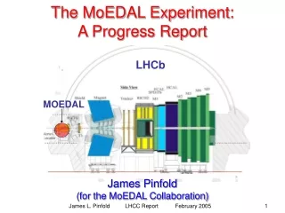
Report of the NTPC Test Experiment in 2007Sep and Others Yohei Nakatsugawa. NTPC test experiment in 2007Sep. ●beam time: 2007Sep 20 – Oct 04 ●test experiment with almost full setup ・ NTPC ・ LEPS spectrometer ・ new LH2 target ・ new drift chamber ・ trigger scintillators

E N D
Report of the NTPC Test Experiment in 2007Sep and Others Yohei Nakatsugawa
NTPC test experiment in 2007Sep ●beam time: 2007Sep 20 – Oct 04 ●test experiment with almost full setup ・NTPC ・LEPS spectrometer ・new LH2 target ・new drift chamber ・trigger scintillators ・magnetic Field 2Tesla
Fwd solenoid dipole outer TPC inner γ new DC AC target Set up ※not scaled
New Liquid Target System ● will be reported by Maeda-san
New Drift Chamber ●will be reported by Sawada-san
2 3 1 6 4 5 Inner Scintillators • ・6 counters (1 for each sector) • ・one-side read out • ・fiber light guide • ・bad time resolution ~800ps RF separation using tagger • will be reported by Yamamura-kun
Outer Scintillators ・12 counters ( 2 for each sector) ・Both sides are read out.( 24 PMT’s) ・time resolution = ~180ps
Forward Scintillators • ・temporary use • ( Top & bottom ones were • used for 1st TPC exp. • The other one is from • ring cyclotron. ) • will be replaced by 4 new ones (designed by Kon-kun)
Trigger Condition ● “Sector” trigger ・ inner ( OR of opposite 4 outers ) e.g. Sector2 trigger = (inner 2) (outer 234 5 ) 4 3 5 2 2 1 6 3 1 2 charged particle on Sector2 3 1 6 4 ・outer = upstream PMT downstream PMT 5 6 4 12 7 5 11 8 ●At least one “Sector” hit should be required. = more than one charged particle in TPC 10 9
Problem & Final Trigger ● magnetic field of solenoid no signal from upstream PMT’s ! (even though PMT’s were covered by iron shields) We could not use coincidence triggers of outer scintillators . Only signal from downstream PMT’s were used as trigger signal of outer. solenoid TPC ●tagger rate was very low ~60kcps inner OR trigger ( (inner 1 2 3 4 5 6 ) AC ~40cps DAQ acceptable rate We used inner OR as main trigger. (minimum bias)
solenoid no signal signal Angle of Upstream PMT ●Best PMT angle was searched during no beam time in November. ●Highest signal was obtained at vertical. ●Additional light guides have been made.
Event Display y y x z
“Circle” Event ●low energy electron? ●inner OR trigger contains too many “circle” events. hadron-like events (events with clean track) … ~10% “Sector” trigger strongly suppress “circle” events. hadron-like events … 80~90% “Sector” hits should be required to reduce trigger rate.
Analysis ●analyzer for newTPC ( NTPCana ) is under construction. ●TPCana modified for newTPC ●main difference … geometry 1st TPC : concentric circle layers , r-φcoordinate newTPC : 6 sectors , x-y coordinate in local sector y x r φ
Analysis ●tracking strategy ・find hits and determine coordinates of hit positions in local sector ・transform from local sector to global system ・find track candidates in global system ・Runge-Kutta tracking in global system and calculate residual in local sector
Analysis ●ExB effect on drift electrons ・ ExB correction already applied to hit position ・ residual of helix fitting was improved. 310 μm 270μm ( no cut of drift length, track angle ) ・ Map of magnetic field was made with RADIA by Yamamura-kun. (Original code of RADIA was made by Ishikawa-san for 1st TPC experiment.)
Analysis y1 ●To Do ・ y coordinate determination using wire ADC ( x : center of gravity of ADC value of pad y : center of gravity of ADC value of wire) identification of wire pulse which corresponds to pad hit ・ dip angle dependence of pad gain Correction of ADC value of pad is needed. dE/dx resolution y2 y y3 y4 y5 x1 x2 x3 x=p3 peakpad ADC cosmic ray data θ CR |θ|<5° 5°<|θ|<10° 10°<|θ|<15° 15°<|θ|<20° 20°<|θ|<25° 25°<|θ|<30° z pad plane
VTZ ●vertex distribution of 2 track event ●Clear shape of LH2 target and CFRP cap can be seen. CFRP cap ~150mm
VTZ of gas target ●LH2 shape disappeared CFRP remained
VTX & VTY vtx vty
dE/dx vs momentum dE/dx momentum * charge[GeV]
Beam Time in 2008 ● NTPC experiment 2008.Jan.25 -- Feb.25 Apr. 5 -- Apr.24 May.12 -- Aug.1
Physics Motivation ●Θ+ photoproduction accompanied by K* meson with deep UV laser (Eg ~ 3GeV) ●TPC can detect decay particles with large acceptance. invariant mass of Θ+ Θ+ K0 + p ππ ● There are some theoretical calculation which suggest decay asymmetry K* from neutron target is sensitive to parity of Θ+.