Download
1 / 39
390 likes | 502 Views
Status report of the DIRAC experiment (PS 212). L.Nemenov. SPS Committee, April 5, 2011. DIRAC collaboration. CERN Geneva, Switzerland. Tokyo Metropolitan University Tokyo, Japan. Czech Technical University Prague , Czech Republic.

E N D
Status report of the DIRAC experiment (PS 212) L.Nemenov SPS Committee, April 5, 2011.
DIRAC collaboration CERN Geneva, Switzerland Tokyo Metropolitan University Tokyo,Japan Czech Technical University Prague, Czech Republic IFIN-HHBucharest, Romania Institute of Physics ASCR Prague, Czech Republic JINRDubna, Russia Nuclear Physics Institute ASCR Rez, Czech Republic SINP of Moscow State UniversityMoscow, Russia INFN-Laboratori Nazionali di FrascatiFrascati,Italy IHEPProtvino, Russia University of MessinaMessina, Italy Santiago de Compostela UniversitySantiago de Compostela,Spain KEKTsukuba, Japan Bern University Bern,Switzerland Kyoto UniversityKyoto, Japan Zurich University Zurich,Switzerland Kyoto Sangyou UniversityKyoto, Japan
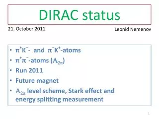
Content • Status of 2008–2010 data process on K+π− and K−π+ atoms. • Schedule of data analysis of K+π− and K−π+ atoms in 2011. • Status of the publication about π+π− atom lifetime measurement on 2001-2003 data • Status of 2008–2010 data process on π+π− atoms. • Multiple-scattering measurement during 2011 run. • Long-lived π+π− atoms and data taking in 2011 for their observation. • K+K− and πμ Coulomb pairs.
DIRAC setup Upgraded DIRAC setup MDC - microdrift gas chambers, SFD - scintillating fiber detector, IH – ionization hodoscope. DC - drift chambers , VH – vertical hodoscopes, HH – horizontal hodoscopes, Ch – nitrogen Cherenkov , PSh - preshower detectors , Mu - muon detectors Modifided parts
π+K− experimental data 2008, 2009 Experimental distribution of π+K− pairs with low background (points with error bar) are fitted with a sum of “atomic pairs”(red line), “Coulomb pairs”(blue line), “non-Coulomb pairs”(magenta line). A sum of “Coulomb” and “non-Coulomb” pairs is presented with black line. The cut on QT<4 MeV/c. 6
K+π− experimental data2008, 2009 Experimental distribution of K+π−pairs with low background (points with error bar) are fitted with a sum of “atomic pairs”(red line), “Coulomb pairs”(blue line), “non-Coulomb pairs”(magenta line). A sum of “Coulomb” and “non-Coulomb” pairs is presented with black line. The cut on QT<4 MeV/c. 7
π+K− experimental data2009 Comparison of the reconstructed π+K −events with low background and 2 SFD planes (red line) and events with medium background and 3 SFD planes (black line). The number of reconstructed events increased by 1.22. 8
K+π− experimental data2009 Comparison of the reconstructed K+π−events with low background and 2 SFD planes (magenta line) and events with medium background and 3 SFD planes (blueline). The number of reconstructed events increased by1.34. 9
All πK experimental data Numbers of generated πK atoms (NA) and numbers of “atomic pairs” (nA) found for data samples of 2008, 2009 and expected for 2010 for data with the low background. * The expected number for events with the medium background will be higher by factor of 1.3 10
All πK experimental data Expected ratio of signal to error for data with the the low background. Accounting of events with medium background increase number of reconstructed events by factor 1.3 and the ratio becomes There is 40% of data with a higher background which implication is under investigation 11
Schedule of data analysis of πK atoms in 2011 I. End of June 2011 1. Preparation of ntuples for 2008, 2009 and 2010 data. 2. Preliminary results on atomic pairs extraction using 2008, 2009 data with low back-ground and two dimension spectra analysis. II End of October 2011 1. Search for πK atomic pairs using two dimension spectra and all statistic with low level background 2. Presentation of preliminary results on the analysis of statistic with low and medium level of back-ground. 12
π+π−data Statistic for measurement of |a0-a2| scattering length difference and expected precision * There is 40% of data with a higher background which implication is under investigation 14
Results: lifetime & scattering length * theoretical uncertainty included in systematic error
Multiple-scattering measurement - 4 planes DC - scatterer - 2 planes DC
Observation of long-livedπ+π−atoms …opens future possibility to measure the energy splitting DE(ns-np). A2π decay dominated by annihilation process: A2π lifetime depends on the ππ scattering length difference |a0 – a2| Energy shift contributions Strong interaction contribution 18
Observation method The A2πdecay in the p-state is forbidden by angular momentum conservation. So the lifetime of the A2πatom in the 2p state (τ2p=1.17 ·10-11 s) is determined by the 2p–1s radiative transition with a subsequent annihilation in 1s state (τ1s=3 ·10-15 s): π+ + π- π0 + π0 The lifetime of the np-states is about 103 larger than the ns-states, so it is possible to measure the energy difference of these levels by exerting an electric field (Stark effect)on the atom and tracking the field dependence of the decay probability. The influence of an magnetic field on the A2π atom lifetime opens the possibility to measure the splitting between 2s and 2p levels. 1s = 2.9 × 10 15 s , 1s = 1.4 × 10 3 cm 2s = 2.3 × 10 14 s , 2s = 1.1 × 10 2 cm 2p = 1.17 × 10 11 s , 2p = 5.7 cm, 3p 19 cm, 4p 43 cm For pA = 4.5 GeV/c ( = 16.1) 19 19
Production yields of A2πlong-lived states Probability of A2π breakup (Br) and production yields of the long-lived states 2p, 3p, 4p, 5p, 6p (m=0) as a function of the target thickness, for Beryllium (Z=4) target. The A2π ground state lifetime is assumed to be 3.0·10-15s and the atom momentum 4.5 GeV/c.
Production yields of A2πlong-lived states • Target material characteristics for production of long-lived atomic states • - target thickness, chosen to provide maximum production yield of long-lived states • A2πbreakup probability • Σ (l ≥ 1):total yield of long-lived states including states with n ≤ 7 • 2p0, 3p0, 4p0, production yield of p-states with magnetic quantum number m = 0 • Σ (l =1, m = 0):sum of the p-states up to n = 7
Simulation of allπ+π- pairs at experimental conditions Part of the atoms, which were created in the Be target and then broken up in the Pt foil, as a function of the distance between Be target and Pt foil for all metastable states (n >1, l >0) and for some individual states with l=1. The foil thickness is 2μ.
y z 90mm x Tokyo Metropolitan University & Kyoto University 60mm 150mm Neodymium magnetic piece=70x60x5mm3: Gap=60mm;BL=0.01TmTime of delivery to CERN: before 4 May 2011
Arrangement of Beryllium target, permanent magnet and Platinum foil. 24
Simulation of long-lived A2π observation Simulated distribution of π+π- pairs over QY with criteria: QX <1 MeV/c, QL < 1MeV/c. Additional magnet is implemented. “Atomic pairs” from long-lived atoms (light area) above background produced in Beryllium target (hatched area)
Simulation of long-lived A2π observation Simulated distribution of π+π- pairs over QL, with criterion QT < 1 MeV/c. “Experimental” data (points with error bars) are fitted by a sum of “atomic pairs” from long-lived states, “Coulomb pairs” and “non-Coulomb pairs”. The background sum is shown by the solid line. The number of atomic pairs are found to be Coulomb pairs atomic pairs from long-lived states non-Coulomb pairs
Simulation of long-lived A2π observation Qy QL Qx Q and F for Be Q<1MeV/c F<2
Simulation of long-lived A2π observation Simulated distribution of π+π- pairs over F, with criterion QT < 2 MeV/c. “Experimental” data (points with error bars) are fitted by a sum of “atomic pairs” from long-lived states, “Coulomb pairs”, “non-Coulomb pairs”. The background sum is shown by the solid line. atomic pairs from long-lived states Coulomb pairs where 0.50, 0.32 and 0.56 Mev/c are RMS’s of the atomic pairs distribution over corresponding components of the relative momentum Q. Now, non-Coulomb pairs
Long-livedπ+π−atoms The observation of ππatom long-lived states opens the future possibility to measure the energy difference between ns and np states DE(ns-np) and the value of ππ scattering lengths |2a0+a2|. If a resonance method can be applied for the DE(ns-np) measurement, then the precision of ππ scattering length measurement can be improved by one order of magnitude relative to the precision of other methods. 29
Measurements of the Lamb shift using external magnetic and electric fields ≡ relative distance between + and mesons in A2 atom z + ≡ laboratory magnetic field ≡ electric field in the CM system of an A2 atom A A2, r B Lab F L.Nemenov, V.Ovsiannikov, Phys.Lett. B514 (2001) Atom beams are influenced by external magnetic field and the relativistic Lorentz factor γ
The dependence of A2π life time eff for 2p-states of the electric field F strength where: BLab = 2 Tesla
Resonant enhancement of the annihilation rate of A2 In Lab. System: at resonance: L.Nemenov, V.Ovsiannikov, E.Tchaplyguine, Nucl. Phys. (2002) l0 In CM System: 33
Resonant method + Resonators 0 0 - 0 A*2 A*A*K 0 0 Pt foil 0 Proton beam p Charged secondary γres1 γres2 γres3 γres4
Coulomb pairs and atoms Strong interaction + p+ p+ p+ K+ K+ p nucleus p- - K- p- p- K- For small Q there are Coulomb pairs : pp, pK, K+K-, πµ C-pairs pp, pK, K+K-, πµ atoms The production yield strongly increases forsmaller Q
Method of A2π observation and measurement Target Ni 98 m π+ A2π p (nA) Atomic pairs (NA) 24 GeV/c π− Interaction point π+ Coulomb correlated pairs (NC) p π− 24 GeV/c ,,,… π+ π+ p Non-Coulomb pairs π− 24 GeV/c η, η’,… π+ Interaction point π0 π+ p Accidental pairs 24 GeV/c π− p