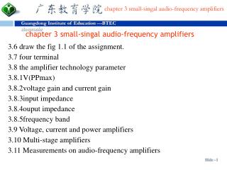
chapter 3 small-singal audio-frequency amplifiers
210 likes | 256 Views
Learn about amplifier technology parameters, voltage/current gains, input/output impedance, frequency bands, measuring methods, and more in small signal audio frequency amplifiers. Explore multi-stage amplifiers and H-parameters of transistors.

chapter 3 small-singal audio-frequency amplifiers
E N D
Presentation Transcript
chapter 3 small-singal audio-frequency amplifiers • 3.6 draw the fig 1.1 of the assignment. • 3.7 four terminal • 3.8 the amplifier technology parameter • 3.8.1V(PPmax) • 3.8.2voltage gain and current gain • 3.8.3input impedance • 3.8.4ouput impedance • 3.8.5frequency band • 3.9 Voltage, current and power amplifiers • 3.10 Multi-stage amplifiers • 3.11 Measurements on audio-frequency amplifiers
The h parameters of a transistor are defined by considering • the transistor to be a four-terminal network(Fig.1.3).If the • input current II and the output voltage Vo are taken to be the • independent variables,then the input voltageVI and the • output current IO can be written down as • VI=IIhI+VOhR (1.1) • IO= IIhF+VOhO (1.2)
In the common-emitter connection: input impedance:
A.C.Load Lines Fig. 3.10 A.C.Load Lines
Current Gain of a Transistor Amplifier Fig. 3.9 Potential-divider bias amplifier Fig. 3.11Current Gain of a Transistor Amplifier ◆When an input signal is applied to a transistor amplifier, the signal current iS super imposed upon the bias current. ◆ suppose that the base bias current is IB2 and that an input signal current swings the base current between the values IB1 and IB3. ◆ The resulting values of collector current are found by projecting onto the collector-current axis from the in tersection of the a.c.load line and the curves for IB1 and IB3.
Current Gain of a Transistor Amplifier Fig. 3.9 Potential-divider bias amplifier Fig. 3.11Current Gain of a Transistor Amplifier
example 3.2 The transistor used in the circuit has the data given in Table. Plot the output characteristics of the transistor. Draw the dc load line and select a suitable operating point. Draw the ac load line and use it to find the alternating current that flows in the 2500Ω load when an input signal producing a base current swing of±15μA about the bias current is applied to the circuit. Assume all the capacitors have zero reactance at signal frequencies. Fig. 3.12example 3.2
Voltage Gain of a FET Amplifier ◆The voltage gain of a fet can also be found with the aid of a load line. For example, Fig. 3.13 shows an ac load line drawn on the drain characteristics of a fet and the dotted projections from the load line show how the drain voltage swing, resulting from the application of an input signal voltage, can be found.The voltage gain Av of the fet amplifier stage is Fig. 3.13 Potential-divider bias amplifier