Download
1 / 26
260 likes | 362 Views
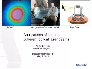
Seeding for Fully Coherent Beams. William S. Graves MIT-Bates. Presented at MIT x-ray laser ASAC committee review Sept 18-19, 2003. Bandwidth and Pulse Length. Seeded beams limited only by uncertainty principle and seed properties. SASE properties determined by ebeam. Master oscillator.

E N D
Seeding for Fully Coherent Beams William S. Graves MIT-Bates Presented at MIT x-ray laser ASAC committee review Sept 18-19, 2003
Bandwidth and Pulse Length Seeded beams limited only by uncertainty principle and seed properties. SASE properties determined by ebeam.
Master oscillator Fiber link synchronization UV Hall X-ray Hall Seed laser Pump laser Seed laser Pump laser Undulators 100 nm Undulators 30 nm 1 nm Injector laser 10 nm 0.3 nm SC Linac 1 GeV 2 GeV 4 GeV 10 nm 3 nm 1 nm Undulators Seed laser Pump laser Nanometer Hall
High Gain Harmonic Generation Method to reach short wavelength FEL output from longer wavelength input seed laser. Input seed at w0 overlaps electron beam in energy modulator undulator. Energy modulation is converted to spatial bunching in chicane magnets. Electron beam radiates coherently at 5w0 in long radiator undulator. Radiator is tuned to 5w0. 5th harmonic bunching is optimized in chicane. Modulator is tuned to w0. Electron beam develops energy modulation at w0.
Single stage HGHG Modulator Dispersion Radiator Seed with low harmonic of conventional laser at 200 – 266 nm, or HHG at 50 – 5 nm. FEL output at 1st – 5th harmonic at 200 – 40 nm, or 50 – 1 nm from HHG. Single HGHG section Use for seeding near final wavelength. Can seed with either short (~10 fs) or long (1 ps) pulse. Ebeam should be matched to needs…0.2 nC for short pulse, 1.0 nC for long pulse.
Data from BNL’s DUV-FEL experiment L.-H. Yu et al, Phys. Rev. Lett. 91.074801, Aug. 2003 HGHG and SASE spectra at 3rd harmonic of seed wavelength (800 nm). Measured data and simulations of HGHG for 2 input seed power levels. • Experiment confirms transform-limited spectral width. • Illustrates modest SASE background from short undulators.
HGHG FEL Simulation • Use code GINGER. • Multidimensional, time dependent, polychromatic. • Model full HGHG cascade: radiation field and electron distribution are passed from stage to stage. • Includes electron beam shot noise and SASE effects. Accurately models frequency dependence of noise amplification. • Some optimization done. Still far to go… Code author W. Fawley of LBNL contributed much to these simulations.
HGHG FEL Simulation • Physics not yet included in model • Full magnetic lattice. Code now assumes uniform constant focusing. • Effect of alignment errors, beam mismatch, undulator errors. • Second order matrix elements in HGHG dispersion sections. • Noise in input seed. • Optical transport and matching between sections. • No sensitivity studies yet.
Cascaded HGHG Stage 1 output at 5w0 seeds 2nd stage Stage 2 output at 25w0 seeds 3rd stage …Nth stage output at 5Nw0 Input seed w0 …Nth stage 1st stage 2nd stage • Factor of ~30 in wavelength is reasonable without additional acceleration between stages. • Seed longer wavelength (100 – 10 nm) beamlines with ~200 nm harmonic from synchronized Ti:Sapp laser. • Seed shorter wavelength (50 – 0.3 nm) beamlines with HHG pulses.
2-stage HGHG cascade with single electron bunch HGHG output pulse Short seed pulse Disturbed e-beam Disturbed e-beam Chicane delay line Electron bunch Mod A Disp A Rad A Mod B Disp B Rad B Monochromator, focusing element, etc • Appropriate for very short seed pulses. • Undulators are short enough that SASE is insignificant.
st = 1.0 fs Power (MW) Power (MW) Power (MW) Time (fs) Time (fs) Time (fs) Intensity (A.U.) Intensity (A.U.) Wavelength (nm) Wavelength (nm) 2-stage, short pulse HGHG simulation output Rad. A output at 1.6 nm Rad. B output at 0.32 nm HHG seed at 8 nm st = 0.66 fs st = 0.64 fs Linear plots of time profiles and spectra of HGHG output from radiators A and B.
2-stage, short pulse HGHG output time profiles Seed at 8 nm. Output at 5th and 25th harmonics from radiators A and B respectively. 1.6 nm 0.32 nm Growth of SASE background is apparent at short wavelength. Due to long undulator, amplification of initial noise.
2-stage, short pulse HGHG output spectra 1.6 nm 0.32 nm
3rd harmonic bunching at 0.1 nm Near saturation, 3rd harmonic bunching reaches 8%, producing substantial radiation (1 mJ) at 0.1 nm from radiator B.
2-stage, long pulse HGHG cascade After delay line, leading pulse is seeded by radiator A output. Uses 2 electron bunches. No fast switch required. Seed trailing e-beam Unseeded e-beam HGHG section B HGHG section A Monochromator, focusing element, etc 0.77 or 1.54 ns delay line
Example: 2-stage, long pulse HGHG cascade Rad. B output at 1.6 nm Rad. A output at 40 nm st = 0.64 fs st = 0.66 fs Power (MW) Power (MW) Time (fs) Time (fs) Wavelength (nm) Wavelength (nm) Seed wavelength = 200 nm Df/frms = 8×10⁻⁵ Df/frms = 4×10⁻⁵
RF deflector for seeding at different energies 1 GeV 1 GeV to 4 GeV to 4 GeV 0.7 ns 1.3 GHz accelerating freq 0.65 GHz deflecting freq At 1 GeV pulses are separated by sub-harmonic RF deflector
4-stage, long pulse HGHG cascade HGHG section B HGHG section D HGHG section A HGHG section C Uses 4 electron bunches. 2 at 1 GeV and 2 bunches at 4 GeV. 40 nm 8 nm 1.6 nm .32 nm Delay Delay 1 GeV 4 GeV
4-stage, long pulse HGHG cascade output 40 nm 2 stages at 1 GeV 2 stages at 4 GeV Power (MW) 8 nm Time (ps) Power (MW) 1.6 nm Time (ps) Power (MW) .32 nm Time (ps) Power (MW) Time (ps) Wavelength (nm) Wavelength (nm) Wavelength (nm) Wavelength (nm)
Low-gain harmonic generation 8 m long undulator for 1.6 nm radiator Coherent spontaneous emission Exponential gain Fawley suggests may have better noise immunity by performing frequency multiplication with CSE of bunched beam. Avoid exponential gain in intermediate stages.
Summary • GINGER is a powerful tool to model HGHG cascades. • Production of sub-fs pulses by seeding with HHG looks promising. • Narrow bandwidth seeding shows potential…needs more work. • Undulator configurations vary for different goals. Will limit options on given beamline. • Next steps • Test performance sensitivity to input parameter variation and errors. • Add missing physics: optical transport, lattice, real dispersion sections. • Reduce noise effects through cascade…test LGHG. • Optimize.
Nanometer Hall to master oscillator for timing sync Direct seeded or cascaded HGHG undulators 10 nm Pump lasers ~20 m length 10 GW peak Ti:Sapp + BBO = 200 nm seed Ti:Sapp + HHG = 10-30 nm seed Tune by OPA or harmonic number Seed lasers Cascaded HGHG undulators 3 nm Cascaded HGHG undulators 1 nm Ti:Sapp + HHG = 10-30 nm seed Tune by OPA or harmonic number ~30 m length 4 GW peak 2 GeV ebeam