Download
1 / 1
10 likes | 223 Views
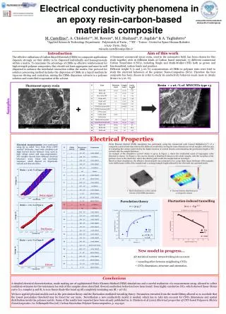
Electrical conductivity phenomena in an epoxy resin-carbon-based materials composite. www.polito.it/micronanotech www.polito.it/carbongroup. M. Castellino* , A. Chiolerio**, M. Rovere*, M.I. Shahzad*, P. Jagdale* & A. Tagliaferro*

E N D
Electrical conductivity phenomena in an epoxy resin-carbon-based materials composite www.polito.it/micronanotech www.polito.it/carbongroup M. Castellino*, A. Chiolerio**, M. Rovere*, M.I. Shahzad*, P. Jagdale* & A. Tagliaferro* *Applied Science & Technology Department - Polytecnich of Turin , **IIT – Torino - Center for Space Human Robotics10129 Turin, Italy micaela.castellino@polito.it Aim of this work A thermoset commercial epoxy resin, used in the automotive field, has been chosen for this study together with 16 different kinds of Carbon based materials: 13 different commercial Carbon NanoTubes (CNTs), including Single and Multi-Walled CNTs both as grown and functionalized, carbon beads and powders. Different weight % (1 and 3 wt.-%) concentrations of CBMs in polymer resin were tried to study the electrical behaviors of the polymer Nano-Composites (NCs). Therefore the best composite has been chosen in order to study its conductivity behavior much more in details (from 1 to 5 wt.-%). Introduction The effective utilization of Carbon Based Materials (CBMs) in composite applications depends strongly on their ability to be dispersed individually and homogeneously within a matrix. To maximize the advantage of CBMs as effective reinforcement for high strength polymer composites, they should not form aggregates and must be well dispersed to enhance the interfacial interaction within the matrix. Our protocol for solution processing method includes the dispersion of CBMs in a liquid medium by vigorous stirring and sonication, mixing the CBMs dispersion solvents in a polymer solution and controlled evaporation of the solvent. Resin + 1 wt.-% of MWCNTs type 13 Thermoset epoxy resin + Samples Electrical Properties Finite Element Method (FEM) simulation was performed, using the commercial code Comsol Multiphysics™, of a composite material slab characterized by different resistivities, having the same dimensions of real samples, with the aim of evaluating the volume interested by the higher fraction of current density and estimating the penetration depth of DC currents into the sample thickness. An example of the simulation control volume is given in Figure 1, where the tetrahedral mesh of Lagrangian cubic elements is shown. In Figure 2, the current density is distributed almost in the whole sample, with the exception of the portions close to the electrodes, where the effective path avoids the sample bottom and edges. Based on these simulations, the effective electrical path was estimated to be: 3 mm thick (same thickness of the sample), 3 cm width (same width of the sample) and 1 cm long (sample length reduced by the electrode size and dead ends). Electrical measurements were performed using the so called “Two Point Probe (TPP) method” (Schroder, 1990) with a Keithley-238 High Current Source Measure Unit, used as high voltage source and nano-amperometer. NCs samples showed three different electrical behaviors: noisy, linear and non-linear responses, which depend on dispersoids amount and characteristics. Resin + 3 wt.-% of type 9 Noisy signal Fluctuation-induced tunnelling Percolation theory Resin + 1 wt.-% of type 3 D . Stauffer, et al. “Introduction to percolation theory.” Taylor and Francis, London, 1994 B . Kilbride, et al., JAP 92, p. 4024, 2002 2- Current density distribution in a composite volume 1- Mesh distribution on the control volume of the FEM simulation Not linear pc = 0.36 v.% t = 1.8 A = 1.44 Resin + 3 wt.-% of type 8 • New model in progress... • 3D statistical resistor network taking into account: • tunneling effect between neighboring CNTs; • CNTs dimensions, structure and orientation. Linear Conclusions A detailed electrical characterization, made making use of sophisticated Finite Element Method (FEM) simulations and a careful realization of a measurement setup, allowed to collect confident estimates for the resistances for each of the samples above described. Several conduction behaviors have been found: from highly conductive NCs, which showed linear Ohmic curve (i.e. samples 3 and 8), to non-linear diode-like trend up till completely insulating one (R > 109W). We have applied physical models such as the percolation theory and the fluctuation-mediated tunneling theory. Parameters extracted from the model fitting allowed us to conclude that the lowest percolation threshold may be found for our resin. Nevertheless a new conductivity model is needed, which has to take into account for CNTs dimensions and spatial distribution inside the polymer matrix. Some of the results here reported have been already published in: A. Chiolerio et al (2011) Electrical properties of CNT-based Polymeric Matrix NanoComposites. In: Yellampalli Siva (ed). Carbon Nanotubes-Polymer Nanocomposites, p. 215-230.