Download
1 / 31
310 likes | 508 Views
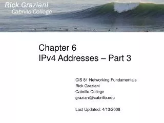
traceroute to www.rsu.ru (195.208.252.130), 30 hops max, 38 byte packets 1 128.4.73.100 (128.4.73.100) 3.587 ms 1.083 ms 1.150 ms 2 128.175.137.1 (128.175.137.1) 3.506 ms 0.993 ms 10.980 ms 3 chp-br1-ge-0-1-0.nss.udel.edu (128.175.111.12) 1.201 ms 1.127 ms 0.814 ms

E N D
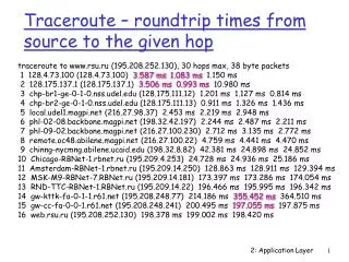
traceroute to www.rsu.ru (195.208.252.130), 30 hops max, 38 byte packets 1 128.4.73.100 (128.4.73.100) 3.587 ms1.083 ms 1.150 ms 2 128.175.137.1 (128.175.137.1) 3.506 ms0.993 ms 10.980 ms 3 chp-br1-ge-0-1-0.nss.udel.edu (128.175.111.12) 1.201 ms 1.127 ms 0.814 ms 4 chp-br2-ge-0-1-0.nss.udel.edu (128.175.111.13) 0.911 ms 1.326 ms 1.436 ms 5 local.udel1.magpi.net (216.27.98.37) 2.453 ms 2.219 ms 2.948 ms 6 phl-02-08.backbone.magpi.net (198.32.42.197) 2.244 ms 2.487 ms 2.211 ms 7 phl-09-02.backbone.magpi.net (216.27.100.230) 2.712 ms 3.135 ms 2.772 ms 8 remote.oc48.abilene.magpi.net (216.27.100.22) 4.759 ms 4.441 ms 4.470 ms 9 chinng-nycmng.abilene.ucaid.edu (198.32.8.82) 42.381 ms 24.898 ms 24.852 ms 10 Chicago-RBNet-1.rbnet.ru (195.209.4.253) 24.728 ms 24.936 ms 25.186 ms 11 Amsterdam-RBNet-1.rbnet.ru (195.209.14.250) 128.863 ms 128.911 ms 129.394 ms 12 MSK-M9-RBNet-7.RBNet.ru (195.209.14.181) 173.397 ms 173.286 ms 174.054 ms 13 RND-TTC-RBNet-1.RBNet.ru (195.209.14.22) 196.466 ms 195.995 ms 196.342 ms 14 gw-kttk-fa-0-1-1.r61.net (195.208.248.77) 214.186 ms 355.452 ms 364.510 ms 15 gw-cc-fa-0-0-1.r61.net (195.208.248.241) 200.495 ms 197.055 ms 197.875 ms 16 web.rsu.ru (195.208.252.130) 198.378 ms 199.002 ms 198.420 ms Traceroute – roundtrip times from source to the given hop 2: Application Layer
HTTP runs over TCP: Client initiates TCP connection (creates socket) to server, port 80 Server accepts TCP connection from client HTTP messages (application-layer protocol messages) exchanged between browser (HTTP client) and Web server (HTTP server) TCP connection closed HTTP is “stateless” Server maintains no information about past client requests HTTP connections 2: Application Layer
Nonpersistent HTTP At most one object is sent over a TCP connection. HTTP/1.0 uses nonpersistent HTTP Persistent HTTP Multiple objects can be sent over single TCP connection between client and server HTTP/1.1 uses persistent connections in default mode HTTP connections 2: Application Layer
User enters URL www.someSchool.edu/index.html 1a. HTTP client initiates TCP connection to HTTP server at www.someSchool.edu on port 80 (contains text, references to 10 jpeg images) Nonpersistent HTTP 1b. HTTP server at host www.someSchool.edu waiting for TCP connection at port 80. “accepts” connection, notifying client 2. HTTP client sends HTTP request message (containing URL) into TCP connection socket. Message indicates that client wants object someDepartment/home.index 3. HTTP server receives request message, forms response message containing requested object, and sends message into its socket time 5. HTTP client receives response message containing html file, displays html. Parsing html file, finds 10 referenced jpeg objects 4. HTTP server closes TCP connection. 6.Steps 1-5 repeated for each of 10 jpeg objects 2: Application Layer
User enters URL www.someSchool.edu/index.html 1a. HTTP client initiates TCP connection to HTTP server at www.someSchool.edu on port 80 (contains text, references to 10 jpeg images) Persistent HTTP 1b. HTTP server at host www.someSchool.edu waiting for TCP connection at port 80. “accepts” connection, notifying client 2. HTTP client sends HTTP request message (containing URL) into TCP connection socket. Message indicates that client wants object someDepartment/home.index 3. HTTP server receives request message, forms response message containing requested object, and sends message into its socket time 5. HTTP client receives response message containing html file, displays html. Parsing html file, finds 10 referenced jpeg objects 7. HTTP server closes TCP connection after it has beenidle for a while. 6.Steps 2-5 repeated for each of 10 jpeg objects 2: Application Layer
Response time modeling • Definition of round trip time (RTT): time to send a small packet to travel from client to server and back. • Response time: • One RTT to initiate TCP connection • One RTT for HTTP request and first few bytes of HTTP response to return • File transmission time • Total = 2RTT+ file transmit time client server initiate TCP connection RTT request file time to transmit file RTT file received time time 2: Application Layer
Nonpersistent HTTP: Requires 2 RTTs per object OS overhead for each TCP connection Browsers often open parallel TCP connections to fetch referenced objects Persistent HTTP: Server leaves connection open after sending response Subsequent HTTP messages between same client/server sent over this open connection Persistent without pipelining: Client issues new request only when previous response has been received One RTT for each object Persistent with pipelining Default in HTTP/1.1 Client sends requests as soon as it encounters an reference As little as one RTT for all the referenced objects Persistent vs. Nonpersistent HTTP 2: Application Layer
Many major Web sites use cookies to store user-related information at user’s computer and retrieve it when needed Four components: 1) Server to client: cookie header line of HTTP response message – set cookie 2) Later, client to server: cookie header line in HTTP request message – send cookie 3) Cookie file is kept on user’s host, managed by user’s browser 4) Server looks up a back-end database at Web site Example: Susan access Internet always from same PC She visits a specific e-commerce site for first time When initial HTTP requests arrives at site, site creates a unique ID and creates an entry in backend database for ID User-server state: cookies 2: Application Layer
client server usual http request msg usual http response + Set-cookie: 1678 Cookie file Cookie file Cookie file amazon: 1678 ebay: 8734 amazon: 1678 ebay: 8734 ebay: 8734 cookie- specific action usual http request msg cookie: 1678 usual http request msg cookie: 1678 usual http response msg usual http response msg cookie- spectific action Cookies: keeping “state” server creates ID 1678 for user entry in backend database access access one week later: 2: Application Layer
What cookies can bring: Authorization Shopping carts Recommendations User session state (Web e-mail) Cookies: Pros and Cons • Cookies and privacy: • Cookies permit sites to learn a lot about you • You may supply name and e-mail to sites • Search engines use redirection & cookies to learn yet more • Advertising companies obtain info across sites 2: Application Layer
Goal: satisfy client request without involving origin server User sets browser: Web accesses via cache Browser sends all HTTP requests to cache Object in cache: cache returns object Else cache requests object from origin server, then returns object to client Web caches (proxy servers) Proxy server HTTP request HTTP request client origin server HTTP response HTTP response HTTP request HTTP response client 2: Application Layer
Cache acts as both client and server Typically cache is installed by ISP (university, company, residential ISP) Why Web caching? Reduce response time for client request Reduce traffic on an institution’s access link Internet dense with caches enables “poor” content providers to effectively deliver content More about Web caching 2: Application Layer
Assumptions Average object size = 100,000 bits Avg. request rate from institution’s browsers to origin servers = 15/sec Delay from institutional router to any origin server and back to router = 2 sec Without caching LAN utilization = 15% (100Kb*15/10Mbps) Access link utilization = 100% Delay per request = 2 sec + milliseconds Caching example origin servers public Internet 1.5 Mbps access link institutional network 10 Mbps LAN institutional cache 2: Application Layer
Possible solution Increase bandwidth of access link to, say, 10 Mbps With increased bandwith, no caching LAN utilization = 15% (100Kb*15/10Mbps) Access link utilization = 15% Delay per request = 2 sec + milliseconds Often a costly upgrade Caching example origin servers public Internet 10 Mbps access link institutional network 10 Mbps LAN institutional cache 2: Application Layer
Possible solution suppose hit rate is 40% With caching 40% requests will be satisfied almost immediately 60% requests satisfied by origin server Access link utilization = 60%(60%*100Kb*15/10Mbps) Delay = 60%*(2sec+milliseconds) 40%*milliseconds ~ 1.2 secs Caching example origin servers public Internet 1.5 Mbps access link institutional network 10 Mbps LAN institutional cache 2: Application Layer
Goal: cache asks the server not to send object if it wasn’t modified since last time this cache has requested this object Cache: specify date of cached copy in HTTP request If-modified-since: <date> Server: response contains no object if cached copy is up-to-date: HTTP/1.0 304 Not Modified HTTP response HTTP/1.0 304 Not Modified HTTP Conditional GET server cache HTTP request msg If-modified-since: <date> object not modified HTTP request msg If-modified-since: <date> object modified HTTP response HTTP/1.0 200 OK <data> 2: Application Layer
Transfer file to/from remote host Client/server model client: side that initiates transfer server: remote host FTP: RFC 959 FTP server: port 21 FTP user interface FTP client FTP server local file system FTP: the file transfer protocol file transfer user at host remote file system 2: Application Layer
FTP client contacts FTP server at port 21, specifying TCP as transport protocol Client logs on over control connection Client browses remote directory over control connection. When server receives a command for a file transfer, it opens a TCP data connection to client TCP control connection port 21 TCP data connection port 20 FTP client FTP server Separate control, data connections • After transferring one file, server closes connection. • Server opens a second TCP data connection to transfer another file. • FTP server maintains “state”: current directory, earlier authentication 2: Application Layer
Sample commands: Sent as ASCII text over control channel USER username PASS password LIST return list of file in current directory RETR filename retrieves (gets) file STOR filename stores (puts) file onto remote host Sample return codes Status code and phrase (as in HTTP) 331 Username OK, password required 125 data connection already open; transfer starting 425 Can’t open data connection 452 Error writing file FTP commands, responses 2: Application Layer
Three major components: User agents Mail servers Simple mail transfer protocol: SMTP User Agent Composing, editing, reading mail messages e.g., Eudora, Outlook, elm, Netscape Messenger Outgoing, incoming messages stored on server user agent user agent user agent user agent user agent user agent SMTP SMTP SMTP mail server mail server mail server outgoing message queue user mailbox Electronic Mail 2: Application Layer
Mailbox contains incoming messages for user Message queue of outgoing (to be sent) mail messages SMTP protocol between mail servers to send email messages client: sending mail server “server”: receiving mail server Mail servers 2: Application Layer
Uses TCP to reliably transfer email message from client to server, port 25 Direct transfer: sending server to receiving server Three phases of transfer Handshaking (greeting) Transfer of messages Closure Command/response interaction commands: ASCII text response: status code and phrase Messages must be in 7-bit ASCII SMTP Protocol [RFC 2821] 2: Application Layer
1) Alice uses user agent (UA) to compose message for bob@someschool.edu 2) Alice’s UA sends message to her mail server; message placed in message queue 3) Client side of SMTP opens TCP connection with Bob’s mail server 4) SMTP client sends Alice’s message over the TCP connection 5) Bob’s mail server places the message in Bob’s mailbox 6) Bob invokes his user agent to read message user agent user agent mail server mail server Alice sends message to Bob 1 2 6 3 4 5 2: Application Layer
Sample SMTP interaction S: 220 hamburger.edu C: HELO crepes.fr S: 250 Hello crepes.fr, pleased to meet you C: MAIL FROM: <alice@crepes.fr> S: 250 alice@crepes.fr... Sender ok C: RCPT TO: <bob@hamburger.edu> S: 250 bob@hamburger.edu ... Recipient ok C: DATA S: 354 Enter mail, end with "." on a line by itself C: Do you like ketchup? C: How about pickles? C: . S: 250 Message accepted for delivery C: QUIT S: 221 hamburger.edu closing connection 2: Application Layer
Try SMTP interaction for yourself: • telnet mail.cis.udel.edu 25 • see 220 reply from server • enter HELO, MAIL FROM, RCPT TO, DATA, QUIT commands above lets you send email without using email client (reader) 2: Application Layer
SMTP uses persistent connections SMTP requires message (header & body) to be in 7-bit ASCII SMTP server uses CRLF.CRLF to determine end of message Comparison with HTTP: HTTP: pull SMTP: push Both have ASCII command/response interaction, status codes SMTP: final words 2: Application Layer
Header lines, e.g., To: From: Subject: differentfrom SMTP commands! Body the “message”, ASCII characters only Mail message format header blank line body 2: Application Layer
MIME: multimedia mail extension, RFC 2045, 2056 Additional lines in msg header declare MIME content type From: alice@crepes.fr To: bob@hamburger.edu Subject: Picture of yummy crepe. MIME-Version: 1.0 Content-Transfer-Encoding: base64 Content-Type: image/jpeg base64 encoded data ..... ......................... ......base64 encoded data Multimedia extensions MIME version method used to encode data multimedia data type, subtype, parameter declaration encoded data 2: Application Layer
SMTP: delivery/storage to receiver’s server Mail access protocol: retrieval from server POP: Post Office Protocol [RFC 1939] Authorization (agent <-->server) and download IMAP: Internet Mail Access Protocol [RFC 1730] More features (more complex) Manipulation of stored msgs on server HTTP: Hotmail , Yahoo! Mail, etc. user agent user agent sender’s mail server SMTP Mail access protocols SMTP access protocol receiver’s mail server 2: Application Layer
authorization phase client commands: user: declare username pass: password server responses +OK -ERR transaction phase, client: list: list message numbers retr: retrieve message by number dele: delete quit POP3 protocol S: +OK POP3 server ready C: user bob S: +OK C: pass hungry S: +OK user successfully logged on C: list S: 1 498 S: 2 912 S: . C: retr 1 S: <message 1 contents> S: . C: dele 1 C: retr 2 S: <message 1 contents> S: . C: dele 2 C: quit S: +OK POP3 server signing off 2: Application Layer
POP3 Previous example uses “download and delete” mode. Bob cannot re-read e-mail if he changes client “Download-and-keep”: copies of messages on different clients POP3 is stateless across sessions IMAP Keep all messages in one place: the server Allows user to organize messages in folders IMAP keeps user state across sessions: Names of folders and mappings between message IDs and folder name POP3 vs IMAP 2: Application Layer