Communications Baseband
The Communications Baseband Project at the Rochester Institute of Technology is designed to enhance students' hands-on understanding of communication systems. Led by Dr. Joe Delorenzo and his team, this project focuses on modulation techniques including Amplitude, Frequency, and Pulse Code Modulation. Students work through 12 subsystems assessing feasibility and compliance with design objectives, while simulating analog and digital transmissions. The project culminates in a fully functional system demonstrating the design and testing of communication protocols.

Communications Baseband
E N D
Presentation Transcript
Communications Baseband Project 05500
Members • Advisors: • Dr. Joe Delorenzo • Dr. Eli Saber • Dr. Sohail Dianat • Team Members: • Leland Smith (Team Leader) • Jason Riesbeck (Chief Engineer) • Jonathan Hutton
Introduction • Communications Baseband is a project created by several professors in order to stimulate student’s practical understanding of communication systems. • Sponsor: Rochester Institute of Technology Department of Electrical Engineering
Project Overview • Modulate/Demodulate using Amplitude Modulation, Frequency Modulation, and Pulse Code Modulation • Receive analog or digital transmission approximately a classrooms distance and demodulate • Output original signal to see/hear successful recovery
System Development •Divided into 12 subsystems •Specification developed for each
Feasibility • Assessed at a subsystem level. • Depends on the resources available • To maintain feasibility, subsystems should: • Satisfy design objectives • Economical • Comply with time constraints
FCC Considerations Unlicensed Bands (FCC 15.247.b.4) Antenna gain can be as much as 6dB. All other bands 100mW or less
Audio Subsystem • Block Diagram Input Output
Anti-Aliasing Filter • Specifications: • 0-5V Input • Pass-band 20 kHz • Stop-band 22 kHz • Attenuation 20 dB • Elliptical Filter
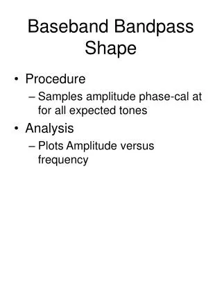
Anti-Aliasing Filter Schematic: Plot:
Anti-Aliasing Filter • 6dB Voltage Level = 3dB Power Level = 1.26V • Output =1.26V @ 20.0 kHz • Attenuation =
AM Subassembly • Block Diagrams
AM Modulation • Carrier • 1 MHz Sine Wave • Modulator • Oscillator Input • Audio Input
Carrier Signal • Clock Oscillator • Square Wave • RLC Filter
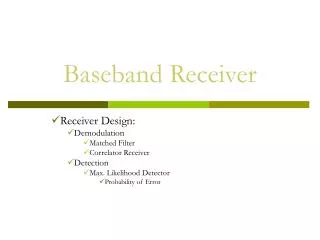
AM Receiver • AM Receiver • Demodulates Signal • Amplifies the Signal by 18 dB
FM Systems • Complicated to engineer • Could take months in industry Transmitter Receiver
Radio IC’s • A simple and effective solution
Design Documentation • Schematics • Parts Lists • Specification Documents • Interconnection Control Documents • Test Procedures • Printed Circuit Board
Design Issues • PCB Short
Design Issues • PCB Short • Voltage Regulator Pin-Out
Design Issues • PCB Short • Voltage Regulator Pin-Out • Tuning Capacitor
Design Issues • PCB Short • Voltage Regulator Pin-Out • Tuning Capacitor • Audio Distortion
Design Issues • PCB Short • Voltage Regulator Pin-Out • Tuning Capacitor • Audio Distortion • Tuning Inductor
Finished Product FM Transmitter FM Receiver
FSK Systems • Similar to analog FM systems • Also very complicated
FSK Feasibility • Nordic NRF2401 • Transmits data at 1Mbps • 2.4GHz ISM band
FSK Link Analysis • NRF2401 Specification ○ 0dBm output power ○ -80dBm receiver sensitivity • Link Budget Analysis ○ 60dB of attenuation at 10m (with 0dB antenna gain)
Design Documentation • Schematics • Parts Lists • Specification Documents • Interconnection Control Documents • Test Procedures • Printed Circuit Board • FSK Protocol Information
PCM and Control Subassembly • Transmit Side • Conversion of Analog to Digital • Apply Protocol to Digital Data • Manage Memory and Data Flow to FSK Chip • Receive Side • Provide Control to FSK Chip • Receive and Manage FSK Chip Data • Control and Send Data to DAC
Interface Specifications • Rail to rail (0-3.3V) analog signal input • Desire >44 kHz Sample Rate • 1 Mbps transmit rate to FSK chip • Send samples to Digital to Analog Converter at sample rate
Solutions • PICmicro Microcontroller • Analog Devices DAC • 10-bit • No overhead bits • Serial • Up to 20 MHz data rate
Capabilities • PIC offers 10-bit AD • PIC provides I/O ports • USART (Synchronous/Asynchronous Communications), and MSSP (Master Synchronous Serial Port for DAC) • Many I/O Ports for control lines • Provides 1MHz USART • Data storage and management
Chosen Microprocessor • PIC18LF2525 • Low voltage at full speed 3.3V @ 32MHz • Internal oscillator up to 32MHz • External interrupts • MSSP • More robust commands
RX FSK-PIC-DAC Interface • Vref = Vdd
Communications Protocol • PIC must manage data from 10-bit samples to exact 1 Mbps output • USART sends 8-bit words and takes care of data rate • The FSK chip offers several protocol options
IN PIC OUT • Known: What goes in must come out – and at the same rate. • Therefore: The rate the PIC can sample at is governed by the FSK communications protocol. • Sampling rate must be some integer number of the outgoing packet rate