Download
1 / 18
180 likes | 258 Views
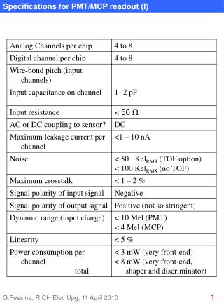
LKr readout system specifications. R. Fantechi 9/2/2011. The CREAM module. Summary of technical parameters. Analog part. Definition of the input parameters and shaping needed 2Vpp dynamic range, AC-coupled, 100 ohm terminated 40 ns rise time, 70 ns FWHM, waveforms as NA48.

E N D
LKrreadout system specifications R. Fantechi 9/2/2011
Analog part • Definition of the input parameters and shaping needed • 2Vpp dynamic range, AC-coupled, 100 ohm terminated • 40 ns rise time, 70 ns FWHM, waveforms as NA48 32 channels/board 2 connectors/board Keep NA48 transceiver-CPD cables
ADC • 14 bit dynamic range, ENOB O(10bit), 40 MHz • Quad or octal package preferred • Serial ADCs, LVDS outputs • Differential inputs • Keep differential paths from connector to ADC input pins • Care with the power supply of the clock drivers • Aperture jitter, modulation with digital noise • Extensive programming and built-in test facilities • 16-bit DAC driven pedestal offset
TTC handling • Trigger board to handle TTC • One for each crate • Receives TTC and distribute signals over the P0 backplane • Plan to use two TTCrx • One has B-channel activity switched off to have the best (O(20ps) clock jitter • Choke/error • Sent by CREAMs through P0 to the trigger board • Fan-in at crate level • Additional fan-in of all crates to LTU • Extensive description of TTC sequences and of our use of L0 messages
Acquisition sequence • ADCs continuosly digitizing at 40 MHz • The data streams from the ADCs are stored in a “circular buffer” • Need to store samples for 10 ms, so 800 Kbytes/channel • First buffer implemented in DDR3, ~12MBytes/16 channels • Extraction from the circular buffer at L0 arrival • A programmable number of samples (typ. 8, max 255) is moved to a “linear buffer” • Time stamped • The dimension should be such to store 1MHz of events for a time of at least 10 seconds • Second buffer implemented in DDR3, 2.56 Gbyte/16 channels • Rationale for a 4GB DDR3 memory (cheap now) • Data are now ready to be read at L1 • To be packed • Optionally zero suppressed • Output through one Gb Ethernet • Will allow to read non-zero suppressed data at 100 KHz with a network bandwith of 400 Mb/sec
L1 processing • L1 request packet received via TCP/IP • It will contain the destination address of the data • IP address + port • It can contain multiple requests • The timestamp field is used to retrieve the interesting data • Which are packed as proposed and sent to L2/EB The “Checksum datum” belongs to the “Detector data”
L0 processing • Addition of the possibility to read data at L0 • Lower rate • For test purposes (i.e. LKr trigger efficiencies) • The format of the data will be the same • A bit in the detector data will indicate L0 data • Time stamp info not as rich as for L1 • Destination addresses • Obviously not in the L0 info • Should be preassigned and assigned with a round-robin mechanism based i.e. on the modulus of the event number
Additional L1 features • L1 request packets sent from L1TP to all CREAMs • However the L1 packet structure allows interesting possibilities • The LKr Trigger could prepare, for specific L0 accepted events a series of packets to request a limited amount of data from the CREAMs • Implementation of Regions Of Interest • Those data could be sent to a L1 processor to do refined computations on single cell data • The data in the CREAMs are not discarded after this operation and are available for a possible L1 readout • Investigated while thinking on LKr L1 • Technically feasible • However, at a first sight, no improvement in rate reduction with such a processing for L0 selected events
Zero suppression • Addition of basic zero suppression • As mentioned, capability to read 100 KHz of non-zero suppressed data within the bandwidth of the links • Problems moved to the receiving ends… • Basic zero suppression to reduce the bulk of data • Implemented during the packing of the data before transmission • At least two possible mechanisms • Cut events where the difference between the minimum and maximum sample values is less than a threshold • Store only the average pedestal for the conditions above • Done cell by cell, no need of cluster reconstruction, halo expansion, access to adjacent boards • Possibility to flag (2 bits free) samples for specific features • Signal above threshold, etc. • Could simplify L2 tasks, i.e. seeds search
Data calibration • Included logic to calibrate ADC data • For trigger sums • In NA48, analog sums where prepared weighting the signals through a DAC-controlled attenuator • In the CREAM, sums are made up with the data from the ADCs • Need to subtract the pedestal • And weight within 25% with 8 bit resolution • Provision for the storage of pedestal and gain table to be loaded at inizialization time • For data • Provision of another table with pedestal and gain values, more precise to be possibly use to calibrate data on-the-fly • Necessary for an alternative readout mode
Feature extraction • Alternative readout • To be possibly implemented when we have the complete control on the operation of the system • Idea: reconstruct time and energy in the CREAM and send continuosly these time-stamped data to a processing system • Build complete events • Interface with the L1 trigger to readout from those PC L1-selected events • Basic specifications • Need to understand rates and the way of coupling to L1 • Could be a firmware upgrade • Firms are requested to give access to the firmware for maintenance and upgrade
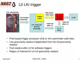
Trigger sums • Preparation for LKr L0 Trigger • The layout of the connectors is such that we can have only 2x8 or 4x4 sums • Programmable choice • Sums are made after the ADCs • 14 bit data, 18 bit effective sum dynamic range • 16 bit sums sent to LKr trigger • Pedestal subtracted and calibrated data • Transmission using serial protocol on copper • Use of commercial serializer/deserializer • Agreement on the type between firm and NA62 (trigger) • Use of Ethernet CAT6 cable • 4 pairs available, up to 4 sums or 2 sums split on two pairs each
System details • VME 6U format • VME64 compliant • Initialization, tests, even a limited data acquisition using VME • Plan to use commercial bridges to connect the crates to a PC • Additional LEMO connectors for test setup • Distribute clock, SOB/EOB, trigger • Also an analog output, DAC-converted programmable sums of channels • To be used in a lab test and acceptance environment
Market survey story V. Ryjov Specification paper 98% ready Some administrative details to be refined i.e. conditions for bid assignment, forms, etc
Expected time schedule • End of February papers to firms • 5 weeks for the response • Selection of the winner before end of April (Finance committee) • Approval by finances due by the end of June • Start prototype development • Prototype expected by end of March 2012 • End of September to complete acceptance tests • In parallel, around End of July, start a pre-production series • Production starting • First half on 1/10/2012, complete delivery at the end of 2012 • Second half on 1/1/2013, complete delivery end of march 2013