Interconnection Networks Contd.
Interconnection Networks Contd. L.N. Bhuyan Partly from Berkeley Notes. More Static Networks: Linear Arrays and Rings. Linear Array Diameter? Average Distance? Bisection bandwidth? Route A -> B given by relative address R = B-A Torus?

Interconnection Networks Contd.
E N D
Presentation Transcript
Interconnection Networks Contd. L.N. Bhuyan Partly from Berkeley Notes
More Static Networks: Linear Arrays and Rings • Linear Array • Diameter? • Average Distance? • Bisection bandwidth? • Route A -> B given by relative address R = B-A • Torus? • Examples: FDDI, SCI, FiberChannel Arbitrated Loop, KSR1 CS258 S99
Multidimensional Meshes and Tori • d-dimensional array • n = kd-1 X ...X kO nodes • described by d-vector of coordinates (id-1, ..., iO) • d-dimensional k-ary mesh: N = kd • k = dÖN • described by d-vector of radix k coordinate • d-dimensional k-ary torus (or k-ary d-cube)? Ex: Intel Paragon (2D), SGI Origin (Hypercube), Cray T3E (3DMesh) 3D Cube 2D Grid CS258 S99
Hypercubes • Also called binary n-cubes. # of nodes = N = 2n. • O(logN) Hops • Good bisection BW • Complexity • Out degree is n = logN correct dimensions in order • with random comm. 2 ports per processor 0-D 1-D 2-D 3-D 4-D 5-D ! CS258 S99
N = 26 nodesS = (sn-1 sn-2… si …s2s1s0)D = (dn-1 dn-2… di… d2d1d0)E-cube routing For i=0 to n-1 Compare si and di Route along i dimension if they differ.Distance = Hamming distance between S and D = the no. of dimensions by which S and D differ.Diameter = Maximum distance = n = log2 N = Dimension of the hypercubeNo. of alternate parts = nFault tolerance = (n-1) = O(log2 N) Routing in Hypercube 000=>001=>011=>111 000=>010=>110=>111 000=>100=>101=>111 CS258 S99
Origin Network • Each router has six pairs of 1.56MB/s unidirectional links • Two to nodes, four to other routers • latency: 41ns pin to pin across a router • Flexible cables up to 3 ft long • Four “virtual channels”: request, reply, other two for priority or I/O CS258 S99
Case Study: Cray T3D • Build up info in ‘shell’ • Remote memory operations encoded in address CS258 S99
Trees • Diameter and ave distance logarithmic • k-ary tree, height d = logk N • address specified d-vector of radix k coordinates describing path down from root • Fixed degree • Route up to common ancestor and down • R = B xor A • let i be position of most significant 1 in R, route up i+1 levels • down in direction given by low i+1 bits of B • H-tree space is O(N) with O(ÖN) long wires • Bisection BW? CS258 S99
Real Machines • Wide links, smaller routing delay • Tremendous variation CS258 S99
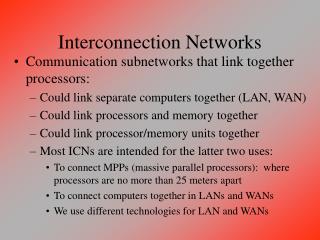
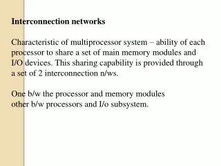
What is Dynamic Network • Dynamic Network is the network that can connect any input to any output by enabling or disabling some switches in the network • Examples: - Shared Bus: The bus arbiter connects a processor to a memory - Crossbar: Consists of a lot of switching elements, which can be enabled to connect many inputs to many outputs simultaneously - Multistage Network: Consists of several stages of switches that are enabled to get connections - The nodes in static networks (like Mesh) also consist of dynamic crossbars CS258 S99
Dynamic Network Consists of Switches Switch Components • Output ports • transmitter (typically drives clock and data) • Input ports • synchronizer aligns data signal with local clock domain • essentially FIFO buffer • Crossbar • connects each input to any output • degree limited by area or pinout • Buffering • Control logic • complexity depends on routing logic and scheduling algorithm • determine output port for each incoming packet • arbitrate among inputs directed at same output CS258 S99
Crossbar Switch Design • Complexity O(N**2) for an NXN Crossbar – Why? See next page CS258 S99
How do you build a crossbar From Control N**2 switches => Cost O(N**2) Time taken by the arbiter = O(N**2) Multiplexors are controlled from controller CS258 S99
Crossbar Contd. • An NXN Crossbar allows all N inputs to be connected simultaneously to all N outputs • It allows all one-to-one mappings, called permutations. No. of permutations = N! • When two or more inputs request the same output, only one of them is connected and others are either dropped or buffered • When processors access memories through crossbar, this situation is called memory access conflicts CS258 S99
Multistage Interconnection Network A network consisting of multiple stages of crossbar switches has the following properties. • NxN network for N=2n • Consists of log2N stages of 2x2 switches • Has N/2 2x2 switches per stage • Cost O(N log n) instead of O(N2) for Crossbar • For N= an,a MIN can be similarly designed with axa switches CS258 S99
Multistage interconnection networks 0 000 1 1 001 2 010 1 3 011 4 100 5 101 6 110 0 7 111 Omega Network and Self Routing Note: Complexity O(Nlog2N) Conflict, less BW than Crossbar, but cost effective; CS258 S99
Example: SP • 8-port switch, 40 MB/s per link, 8-bit phit, 16-bit flit, single 40 MHz clock • packet sw, cut-through, no virtual channel, source-based routing • variable packet <= 255 bytes, 31 byte fifo per input, 7 bytes per output, 16 phit links • 128 8-byte ‘chunks’ in central queue, LRU per output • run in shadow mode CS258 S99
Switching Techniques • Circuit Switching: A control message is sent from source to destination and a path is reserved. Communication starts. The path is released when communication is complete. • Store-and-forward policy (Packet Switching): each switch waits for the full packet to arrive in switch before sending to the next switch (good for WAN) • Cut-through routing or worm hole routing: switch examines the header, decides where to send the message, and then starts forwarding it immediately • In worm hole routing, when head of message is blocked, message stays strung out over the network, potentially blocking other messages (needs only buffer the piece of the packet that is sent between switches). CM-5 uses it, with each switch buffer being 4 bits per port. • Cut through routing lets the tail continue when head is blocked, storing the whole message into an intermmediate switch. (Requires a buffer large enough to hold the largest packet). CS258 S99
Store and Forward vs. Cut-Through • Advantage • Latency reduces from function of:number of intermediate switches X by the size of the packet totime for 1st part of the packet to negotiate the switches + the packet size ÷ interconnect BW CS258 S99
Store&Forward vs Cut-Through Routing • h(n/b + D) vs n/b + h D • what if message is fragmented? • wormhole vs virtual cut-through CS258 S99
Example Q. Compare the efficiency of store-and-forward (packet switching) vs. wormhole routing for transmission of a 20 bytes packet between a source and destination, which are d-nodes apart. Each node takes 0.25 microsecond and link transfer rate is 20 MB/sec. Answer: Time to transfer 20 bytes over a link = 20/20 MB/sec = 1 microsecond. Packet switching: # nodes x (node delay + transfer time)= d x (.25 + 1) = 1.25 d microseconds Wormhole: (# nodes x node delay) + transfer time = 0.25 d + 1 Book: For d=7, packet switching takes 8.75 microseconds vs. 2.75 microseconds for wormhole routing