Download
1 / 24
450 likes | 757 Views
phase-lead compensator design. 20loga. 10loga. 0 dB. -1/aT. -1/T. ω m. 0 O. Properties of phase-lead compensator. a>1. |G c | dB. |G c (jω m )| dB =10loga. Maximum phase contributed at ω m. Geometric mean of singularities. Φ m. G c. Note that. |G c (jω m )| dB =10loga.

E N D
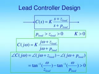
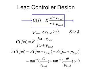
phase-lead compensator design 10.3 Phase-Lead Compensation
20loga 10loga 0 dB -1/aT -1/T ωm 0O Properties of phase-lead compensator a>1 |Gc|dB |Gc(jωm)|dB=10loga Maximum phase contributed at ωm Geometric mean of singularities Φm Gc 10.3 Phase-Lead Compensation
Note that |Gc(jωm)|dB=10loga 10.3 Phase-Lead Compensation
ωg gain 0 dB phase 180o Amount to be contributed by Gc Desired PM ΦD Phase available (plant) ΦA 10.3 Phase-Lead Compensation
ωg ω’g gain 0 dB ΦD phase 180o A naive idea Let Φm= ΦD -ΦA ωm= ωg Unavoidable! New PM ΦA Less than desired ? ! 10.3 Phase-Lead Compensation
ωg gain 0 dB phase 180o Why? Gain crossover shifts to right ω’g ωg 1.Phase available from plant, less than ΦA 2.Phase available from compensator, less than Φm 10.3 Phase-Lead Compensation
Measures to be taken • 1. Add some safety to Φm • usually about 5o 2. Choose ωm = ω’g ! How! 10.3 Phase-Lead Compensation
ωg ω’g 10loga gain 0 dB -10loga phase 180o ω’g : frequency at which |GH|=-10loga Let ωm =ω’g Φm fully utilized! 10.3 Phase-Lead Compensation
Procedure Specs: steady-state error & phase margin Determine the gain compensation for desired st.st. error 1 K Sketch Bode plot & determine phase margin for KGH 2 ΦA Safety 5o-10o 3 Φm Φm = ΦD - ΦA + ε 4 a 10.3 Phase-Lead Compensation
Procedure cont’d 5 Find ωm = ω’g |KGH(jωm)|= -10loga ωm 6 T 7 Gc 10.3 Phase-Lead Compensation
Final check 8 Sketch Bode plot for KGcGH & check results If not satisfactory, go back & modify (Increase safety??) 10.3 Phase-Lead Compensation
Remarks Phase margin increased Improved relative stability Smaller overshoot Gain crossover shifted to right ω’g ωg Larger band-width More susceptible to noise Faster 10.3 Phase-Lead Compensation
Further remarks Fails if : Phase characteristics is too steep Drop in ΦAis large Gain characteristics is too flat Shift in ωg is large Drop in ΦAis large 10.3 Phase-Lead Compensation
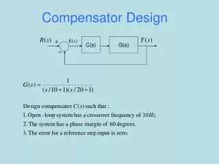
Example Specs: Steady-state error to unit ramp 10% PM > 30o 10.3 Phase-Lead Compensation
Step 1 Earlier example: K=20 Satisfies the st.st. error requirement 10.3 Phase-Lead Compensation
Bode Diagrams 60 40 20 0 Phase (deg); Magnitude (dB) -100 -120 -140 -160 -180 -1 0 10 10 Frequency (rad/sec) Step 2 Bode plot for Gm = Inf, Pm=13.669 deg. (at 4.5152 rad/sec) and PM. Yields PM=ΦA=13.669o at ωg=4.5 rad/sec. 10.3 Phase-Lead Compensation
Steps 3&4 Φm = ΦD - ΦA + ε = 30o - 13.669o + ε = 16.331 + ε Φm = 21.331o Take safetyε=5o a=2.143 10.3 Phase-Lead Compensation
20 10 -3.31 dB 0 -10 Phase (deg); Magnitude (dB) -120 -140 -160 0 1 10 10 Frequency (rad/sec) Step 5 Determine the frequency at which |KGH|= -10loga = -10log2.143= -3.31 6.45 rad/s Yields 6.45 rad/sec ωm = 6.45 rad/sec 10.3 Phase-Lead Compensation
Step 6&7 T 0.125 10.3 Phase-Lead Compensation
Bode Diagrams Gm = Inf, Pm=32.473 deg. (at 5.4525 rad/sec) 60 40 20 0 -20 -40 Phase (deg); Magnitude (dB) -100 -120 -140 -160 -180 -1 0 1 10 10 10 Step 8 Bode plot of the compensated system Yields PM=32.47o 10.3 Phase-Lead Compensation
Step Response Closed Loop Bode Diagrams 1.6 1.4 0 1.2 -20 1 -40 Amplitude Phase (deg); Magnitude (dB) 0.8 0 0.6 -50 0.4 -100 0.2 -150 0 0 1 2 3 4 5 -1 0 1 2 10 10 10 10 Time (sec.) Frequency (rad/sec) Overall check 10.3 Phase-Lead Compensation
Evaluation of results Overshoot reduced 60 40% Settling time reduced 10 2 sec Rise-time reduced somewhat Resonance peek reduced 10.3 Phase-Lead Compensation
Plant Uncompensated Compensator Compensated RL interpretation 10.3 Phase-Lead Compensation
End of Section Next section Restart section Restart chapter i The End General index End show 10.3 Phase-Lead Compensation