Object-Oriented Software Design: The Design Phase in SDLC
Discover the Design Phase in the Software Development Life Cycle, including Architectural and Detailed Design levels, UML classes, interfaces, associations, and inheritance concepts. Enhance your understanding of good design practices.

Object-Oriented Software Design: The Design Phase in SDLC
E N D
Presentation Transcript
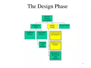
Design Phase • The objective of this section is to introduce an approach to object oriented software design. When you have read this section you will: • know the most important activities in a general object oriented design process ; • understand different models that may be used to document an object oriented design; • have been introduced to the representation of these models in the Unified Modeling Language. Unit 22
What is Design? • The next step in the SDLC is the Design phase which translates the requirements into the solution. • During the design phase, the designers decide how the software system should satisfy the requirements identified during the Requirements Phase. Unit 22
The levels of Design Phase • The Software Design phase has two levels: • Architectural Design – This associates the system capabilities identified in the requirements specification with the system components that will implement them. Components are usually modules, and the architecture also describes the interconnections among them. In addition, the architecture defines the hierarchies that create systems from subsystems. • Detailed Design – It addresses the code design of each module. This involves algorithms, data structures and procedures. Unit 22
Characteristics of Good Design Let us discuss the attributes that reflect design quality: • Component independence - Are the components reusable, portable and expandable in the future? • Exception Identification and Handling – Is exception handling properly embedded in the design so that the system will be secured and autonomous? • Fault Prevention and Fault Tolerance – Do designers anticipate faults and handle them in ways that minimize disruption and maximize safety? Do designers guard against faults built into each component, as well as against faults introduced by other components, systems, and interfaces? Unit 22
UML Classes and Java Templates • The Unified Modeling Language (UML) provides a very robust notation which grows from analysis into design. Certain elements of the notation (for example, classes, associations, aggregations, inheritance) are introduced during the design phase. • Here we discuss the relationship between UML representation of Java classes. We explain the concepts by example. Here in this section we study how the Object Oriented concepts of classes, composition, aggregation, inheritance and interfaces are represented in both UML and Java language Unit 22
UML Class Icon • The icon that represents a class is the fundamental element of the class diagram. • The icon is shown as a rectangle divided into three compartments. class Point { private double itsX; private double itsY; public Point (double x, double y) { ... } public double getX() {…} public double getY() {…} public Point add (Point p) {…} } Point itsX : double itsY : double Point() getX() getY() add() Unit 22
UML Interfaces • The primary icon for an interface is like a class except that it has a special • denotation called a stereotype. interface Employee { String itsName=“Ali”; public String name(); public Money calculatePay(); } <<Interface>> Employee itsName : String name() calculatePay() Unit 22
UML Navigable Associations • An association captures the static relationship between entities: one object having • having another as an attribute or being related in the sense of owning. class Employee { // ... private BenefitsPackage itsBenefits; } class BenefitsPackage { // ... No reference to the owning Employee class } Unit 22
UML Associations • UML relationships are presumed to be bi-directional unless the arrow head is • present to restrict them. class Employer { // ... private Employee itsWorker; } class Employee { // ... private Employer itsBoss; } Unit 22
UML Multiplicity • UML multiplicity is used to specify the relationship between an • instance of one class and instances of another class. • Possible multiplicity annotations are: • 1 - Exactly One • * or 0..* or 0..n - Zero or More • 1..* or 1..n - One or More • 2..10 - 2 to 10 (an exact range) Unit 22
UML Multiplicity Employee TimeCard itsName : String itsCards[] : TimeCard 1..* 1..* name() calculatePay() class Employee { // ... private TimeCard itsCards[ ]; // … } Unit 22
UML Composition class Telephone { // ... private Speaker itsSpeaker; private Microphone itsMic; private Dialer itsDialer; private Button itsButtons[]; } Unit 22
UML Aggregation vs. Composition class Car { Wheel getWheel (int n) { return itsWheels[n]; } // ... private Wheel itsWheels[]; private Chassis itsChassis; } class TireCenter { void inspectTire (Car c) { Wheel w = c.getWheel (1); g = new TireGuarantee (w); StoreInDatabase (g); } } Unit 22
UML Inheritance (Generalization) Unit 22
UML Inheritance Generalization (cont’d) abstract class Employee { public String name() { return itsName; } public abstract Money calculatePay(); private String itsName; } class HourlyEmployee extends Employee{ public Money calculatePay() { // Sum up all the timecard to calculate pay } } class SalaryEmployee extends Employee{ public Money calculatePay() { return itsFixedSalary; } } Unit 22
UML Interface Realization (cont’d) interface Command { void DoIt (); } class PrintCommand implements Command{ public void DoIt () { // send a document to the printer } } Unit 22
Example 1 class Student { // ... private String name; private int studentID; private Course semCourses[ ]; public void setCourses( ); public void changeCourses( ); } class Course { // ... private String name; private int courseID; public int getCourseID( ); public String getName( ); } Unit 22
UML Diagram for Example 1 Unit 22
Example 2 class University{ // ... private String name; private String address; private Department itsDepts[ ]; private Professor itsProfs[ ]; public University( Department[ ] X ) { itsDepts = X;} public void appointProfs( Professor[ ] X ) { itsProfs = X;} } class Department { // ... private String name; private int buildingLocation; } class Professor { // ... private String name; private DOB birthDate; private String qualification; } Unit 22
1 1 1..* 1..* UML Diagram for Example 2 Unit 22
Quiz • Draw the UML diagram for the following java templates. Class University{ // ... private Employee itsEmployees[ ]; private Student itsStudents[ ]; public void appointEmployee( ); public void admitStudent( ); } class Employee { // ... private String name; private Date dateOfAppointment; public void name( ){ } public void calculatePay( ) { } } interface Student { // ... public void setCourses( ); public void changeCourses( ); } Class TeachingStaff extends Employee{ // ... private String qualification; } class NonTeachingStaff extends Employee { // ... private String position; } class UndergradStudent implements Student { // ... private Date dateOfAdmission; } class GraduateStudent implements Student { // ... private boolean isThesis; } Unit 22
A Design Process • The design process follows from the Requirements Phase. There are several theories and methods of design process. Here we discuss a simple design process. • Identify the classes and objects. • Describe the object collaborations and the classes. • Design the class diagram. • Sketch the user interface. Unit 22
1. Identifying Classes and Objects An effective way to identify classes is by preparing what are known as Class-Responsibility-Collaboration (CRC) cards. Unit 22
Preparing CRC Cards • Classes – Read through the problem summary statement and identify nouns and noun phrases, placing them on a list. When the list is complete, review it for possible classes, which may be physical objects, concepts, categories of objects, or attributes of other objects. • Responsibilities – Responsibilities relate to actions. A good starting place for finding responsibilities is in the verbs of the problem summary statement. List the verbs, decide which of them represent responsibilities that must be discharged by some class, and allocate each such responsibility to a class. • Collaborations – Simply scan the list of responsibilities of each class and identify any other class it needs in order to fulfill its responsibilities. List these as its collaborations. Unit 22
How do we Find Classes? • One approach for identifying classes is to use the noun phrases of the itemized requirements which is normally in simple English. • Normally the nouns are used to extract the classes and the verbs are used to identify the methods of the classes. • Here we rewrite the requirements (Problem Summary Statement) and mark the nouns in red color and verbs in pink color. Unit 22
Problem Requirements: Listing Nouns and Verbs Initially acustomeropensanaccountwith 500 riyals. The customertracksthebalancein his account through the ATM. There are two buttons on the screen of ATM:WithdrawandDeposit. The customer can withdrawmoneyfrom his account, whichdecreaseshis balance. The customer can deposit money in his account, whichincreaseshis balance. Whenever money is withdrawn or deposited, amessageisdisplayedconfirming the action. If the customer tries to withdraw money, which is more than the balance, an error message is displayed. Here is a restriction on the ATM transaction of a customer. A customer can withdraw or deposit exactly 50 riyals at a time. Unit 22
Finding classes – CRC cards The possible classes may becustomer andaccount. Thebalancemay be an attribute in the class account. Themoneyandmessagemay be parameters passed to methods. Unit 22
Finding Classes – CRC Cards Unit 22
2. Object Collaborations and Classes 2.1. Recall the use case diagram: Unit 22
2.2. Preparing Collaboration Diagram: 2.2.1. A collaboration diagram for thewithdraw use-case Unit 22
2.2.2. A Collaboration Diagram for theDeposit use-case Unit 22
3.1. Preparing class diagram: 3. Designing the Class Diagram Unit 22
Java Templates • Here is the corresponding java templates of the class diagram. There are two java files: Account.java and Customer.java. Unit 22
Template of Customer.java // file Customer.java public class Customer { private final static int INITIAL_BAL = 500; private Account theAccount = new Account ( INITIAL_BAL ); public void init( ){ //if Withdraw Button is pressed then //theAccount.withdraw(this) and display theAccount.getBalance( ); //if Deposit Button is pressed then //theAccount.deposit(this) and display theAccount.getBalance( ); } public void tellResult(String msg) { //display the message in the applet } } Unit 22
Template of Account.java // file Account.java public class Account{ private int balance; public Account(int qty) { //balance = qty; } public void withdraw(Customer theCustomer) { // subtract the amount from the balance //theCustomer.tellResult(…); } public void deposit(Customer theCustomer) { // add the amount to the balance //theCustomer.tellResult( ){…} } public int getBalance( ) { //return balance; } } Unit 22
4. Sketching the User Interface • The final step in designing an object oriented program is designing its user interface. The user interface is important to the user, because it is the part of the system that is visible. It is important to show the user, as soon and as accurately as possible, what the user interface will look like. • You can sketch a user interface using pencil and paper, or you can use a drawing program. But, the best way to sketch a user interface is using your java integrated development environment (IDE). Unit 22
User Interface Design Welcome to Riyadh Bank This is Paul Manuel's Account you have an initial deposit of 500 riyals. To withdraw money, just press Withdraw. To deposit money, just press Deposit withdraw deposit Your Balance: 500 Message: Thanks for your business -- come back soon. Unit 22
HTML Templates • Here is the corresponding html template of the user interface diagram. There is a html file - Bank.html. Unit 22
Template of Bank.html // file Bank.html <HTML> <HEAD> <TITLE>This is a Banking Software </TITLE> </HEAD> <BODY> … </BODY> </HTML> Unit 22
Exercises Design a UML model for the following project: You have been asked to develop a banking system for M&P Banking. Hardware and network portion has already been bought. You need to write software to manage savings and checking account transactions as well as ATM services. M&P has one kind of savings and two kinds of checking accounts. The savings account bears interest at the prevailing rates, compounded monthly. Savings transactions are free as long as they are carried out at a branch and not at an ATM. Two checking account options exist. The Rich Club Account (RCA) bears interest at 1 percent less than the savings account rate, checks are free, and no monthly fee is applied as long as the total balance of all accounts is at least $5,000. The Poor Slob Club (PSC) has no minimum balance. PSC accounts are charged a monthly fee of $5.00 and each check costs the customer $0.10. Unit 22