Download
1 / 44
510 likes | 1.35k Views
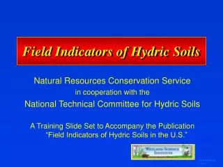
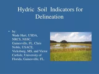
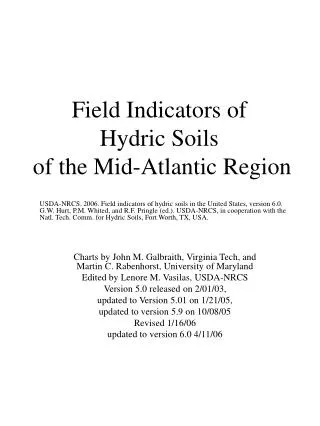
Field Indicators of Hydric Soils in the United States. Version 7.0 and errata and all info on hydric soils can be downloaded from the NTCHS website at http://soils.usda.gov/use/hydric/ . Field Indicators. Field indicators are soil morphological features used to identify hydric soils

E N D
Version 7.0 and errata and all info on hydric soils can be downloaded from the NTCHS website at http://soils.usda.gov/use/hydric/.
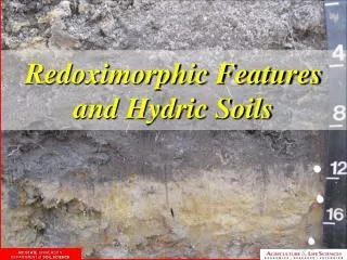
Field Indicators • Field indicators are soil morphological features used to identify hydric soils • The features result from soil genesis in the presence of “anaerobic conditions” • They are used for on-site verification
Development of Field Indicators • Continuous process • On-going since mid-80’s • Inter-agency • Including universities, private sector, federal, state, and local agencies • Multi-disciplinary • Soil scientists, hydrologists, botonists
Hydromorphic Processes • Reduction, translocation, and precipitation of iron and manganese • Accumulation and differential translocation of organic matter • Reduction of sulfur
Hydric Soil Indicators • Indicators are not intended to replace or relieve the requirements contained in the Hydric Soil Definition • Indicators are used to identify the hydric soil component of wetlands; however, there are some hydric soils that lack one of the currently listed indicators
Iron • Many indicators are based on iron reduction, transformation, and differential accumulation.
Carbon • Many indicators are based on carbon accumulation and differential decomposition
Carbon and Iron • Some indicators are based on carbon accumulation and differential decomposition and iron reduction, translocation, and differential accumulation.
Carbon and/or Iron • One indicator is based on carbon accumulation and differential decomposition and/or iron reduction, translocation, and differential accumulation: • S6 Stripped Matrix.
Carbon and Iron/Manganese • One indicator is based on carbon accumulation and differential decomposition and iron/manganese reduction, translocation, and differential accumulation: • F16 High Plains Depression
Iron/Manganese • One indicator is based on iron/manganese reduction, transformation, and differential accumulation: • F12 Iron-Manganese Masses
Sulfur • One indicator is based on sulfur reduction: • A4 Hydrogen Sulfide
Algae • One indicator is based on precipitation of calcium carbonate by algae: • F10 Marl
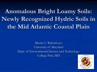
Not all indicators require a chroma 2 or less F8 Redox Depressions F19 Piedmont Flood Plain Soils F20 Anomalous Bright Loamy Soils Chroma 2 or less
Field Indicators of Hydric Soils in the United States • Refinement of the 1987 indicators • Low chroma colors, mottles • Gleyed colors • “High” organic matter content • Organic streaking • Histosol, histic epipedon • Sulfidic material • Address problem soils and situations
Proof positive • If it meets a Field Indicator it is a hydric soil • If it does not meet a Field Indicator it may still be a hydric soil if it meets the definition of a hydric soil
Listed by Land Resource Region Addresses “Problem” soils Mollisols and vertisols Sandy soils Flooded and ponded soils Red parent material Regional
Control Sections or Zones • Layers with: • High value, low chroma or; • Redoximorphic features or; • Organic matter accumulations • At at depth • Of a certain thickness
Field Indicators Glossary • An * indicates a definition in the glossary that is different from other references such as Soil Taxonomy, Soil Survey Manual, National Soils Handbook, and Field Book for Describing and Sampling Soils.
Important Definition • Depleted matrix • Gleyed matrix • Organic soil material (muck, mucky peat, and peat) • Mucky mineral
All color requirements are for moist color. Features are usually more readily identifiable in moist state; they may be hard to see or missing if the soil is too wet, or too dry. Moist Color
The range in colors for the depleted matrix is value 4 or more and chroma 1 or 2; however, colors of value 4 and chroma 1 or 2 and value 5 and chroma 2 must have redox concentrations. Depleted Matrix
A, E, and Calcic Horizons • A, E, and calcic horizons are excluded from the concept of a depleted matrix unless common or many, distinct or prominent redox concentrations as soft masses or pore linings are present.
All colors found on the gleyed pages with value ≥ 4. The range of colors for the gleyed matrix is value 4 or more on either of the two color charts. Gleyed Matrix
Soils that have high value and low chroma in situ but color changes when exposed to air Reduced iron is present Iron is oxidized upon exposure Reduced Matrix
Color of organic soil material may be important Muck – sapric material Mucky peat – hemic material Peat – fibric material Organic Soil Material
Mucky Modified Textures • Mucky modified mineral soil has 0% clay and between 5 and 12% organic carbon, 60% clay and between 12% and 18% organic carbon, or intermediate amounts of clay and intermediate amounts of organic carbon.
Three Major Divisions • All soils • Use regardless of texture • Mostly organic based indicators • Sandy soils • Loamy soils • Use sandy indicators in sandy layers, and loamy indicators in loamy layers
Indicators Format • Alpha numeric symbol • Short name • Applicable Land Resource Region • Description of the indicator • User notes
Rules for Field Indicator Use • A chroma of 2 or less means that the chroma cannot be higher than 2 • Except for F8, F12, F19, F20, and F21 all mineral Field Indicators must have less then 15 cm (6 in) of a chroma > 2 above the indicator.
Soil Surface • The soil surface for Field Indicators A1, A2, A3, S2, and S3 begins at the actual surface. • In LRRs W, X and Y for all other Field Indicators measurements begin at the mineral soil surface. • For all other LRRs all other Field Indicators the measurements should start at the muck or mineral surface.
Combining Indicators • It is permissible to combine certain hydric soil indicators if all requirements of the indicators are met except thickness • The most restrictive requirements for thickness of layers in any indicators used must be met
Minimum Thickness Requirements for Commonly Combined Indicators • S5 – Sandy Redox 4 in. (10 cm) thick starting within 6 in. (15 cm) of the soil surface • S7 – Dark Surface 4 in. (10 cm) thick starting within 6 in. (15 cm) of the soil surface • F1 – Loamy Mucky Mineral 4 in. (10 cm) thick starting within 6 in. (15 cm) of the soil surface • F3 – Depleted Matrix 6 in. (15 cm) thick starting within 10 in. (25 cm) of the soil surface • F6 – Redox Dark Surface 4 in. (10 cm) thick entirely within the upper 12 in. (30 cm) • F7 – Depleted Dark Surface 4 in. (10 cm) thick entirely within the upper 12 in. (30 cm)
Example of a Soil That is Hydric Based on a Combination of Indicators • 3-6 inches meets F6 Redox Dark Surface, but thickness requirement is 4 inches • 6 to 10 inches meets F3 Depleted Matrix requirements, but thickness requirement is 6 inches • Add the 3-6 inch and 6 to 10 inch layer thicknesses together to get 7 inches which is thicker than the most restrictive requirement of 6 inches
Example of a Soil That is Hydric Based on a Combination of Indicators • 0 to 3 inches meets F6 Redox Dark Surface, but thickness requirement is 4 inches • 3 to 6 inches meets S5 Sandy Redox, but thickness requirement is also 4 inches • Combine the thickness of the 2 layers to get 6 inches
Key to Soils that Lack Field Indicators • Dig a hole to 6 in. • Do organic soil materials or mucky modified layers exist? • Does chroma≤ 2 exist? • Are there any distinct or prominent redox concentrations as soft masses or pore linings? • Is there a hydrogen sulfide odor? • Do stripped zones in a sandy layer exist? • Are you in red parent material, a depression, on a floodplain, or within 200 m of an estuarine marsh and 1 m of mean high water? • If answer is no to all questions, the soil will not meet an indicator.
Summary • Field Indicators are soil morphological features used to identify hydric soils • It is important to understand some of the terminology, concepts, and rules in order to use the Field Indicators of Hydric Soils in the United States