Download
1 / 19
210 likes | 598 Views
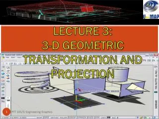
LECTURE 3: 3-D GEOMETRIC TRANSFORMATION AND PROJECTION. 3D PROJECTION. Three different types of 3-D projections are available in most CAD software: isometric, trimetric, and perspective. These three views of a cube are shown in figure below. 1. ISOMETRIC PROJECTION.

E N D
LECTURE 3: 3-D GEOMETRIC TRANSFORMATION AND PROJECTION PTT 105/3: Engineering Graphics
3D PROJECTION • Three different types of 3-D projections are available in most CAD software: • isometric, • trimetric, and • perspective. • These three views of a cube are shown in figure below. PTT 105/3: Engineering Graphics
1. ISOMETRIC PROJECTION • The isometricprojection has a standard orientation that makes it the typical projection used in CAD. • In an isometric projection, the width and depth dimensions are sketched at 30° above horizontal. • This results in the three angles at the upper front corner of the cube being equal to 120°. • The three sides of the cube are also equal, leading to the term iso (equal) -metric (measure). PTT 105/3: Engineering Graphics
Isometric drawings work quite well for objects of limited depth. • However, an isometric drawing distorts the object when the depth is significant. • In this case, a pictorial perspective drawing is better. PTT 105/3: Engineering Graphics
2. TRIMETRIC PROJECTION • In general, the trimetric projection offers more flexibility in orienting the object in space. • The width and depth dimensions are at arbitrary angles to the horizontal, and the three angles at the upper front corner of the cube are unequal. PTT 105/3: Engineering Graphics
This makes the three sides of the cube each have a different length as measured in the plane of the drawing; hence the name tri-metric. • In most CAD software, the trimetric projection fixes one side along a horizontal line and tips the cube forward. • Generally, small manufactured objects are adequately represented by isometric or trimetric views. PTT 105/3: Engineering Graphics
3. PERSPECTIVE PROJECTION • A simply perspective (pictorial perspective) projection is drawn so that parallel lines converge towards a single point, unlike isometric or trimetric projections where parallel lines remain parallel. • This has the effect that distant objects appear smaller than nearer objects. • A perspective projection is quite useful in providing a realistic image of an object when the object spans a long distance such as the view of a bridge, railways or aircraft from one end. PTT 105/3: Engineering Graphics
Two types of pictorial sketches are used frequently in freehand sketching: • isometric and • oblique. • The isometric projection is often used in freehand sketching because it is relatively easy to create a realistic sketch of an object. • But the oblique projection is usually even easier to sketch. • The figure compares an isometric and an oblique projection of a cube with a hole in it. • oblique freehand sketching easier than isometric sketching. PTT 105/3: Engineering Graphics
Differences between 3D and 2D PTT 105/3: Engineering Graphics
3D Term Frequently Used PTT 105/3: Engineering Graphics
4 types of model used in 3D PTT 105/3: Engineering Graphics
Reasons For Using 3D PTT 105/3: Engineering Graphics
3D Capabilities of AutoCAD PTT 105/3: Engineering Graphics