Horizontal Joint Gasket Failure
370 likes | 386 Views
Learn how Finite Element Analysis was used to resolve split case gasket failure in an Ingersoll Rand pump, increasing reliability and reducing downtime. Presented by Kurt J. Weis from Rotating Equipment Repair, Inc.

Horizontal Joint Gasket Failure
E N D
Presentation Transcript
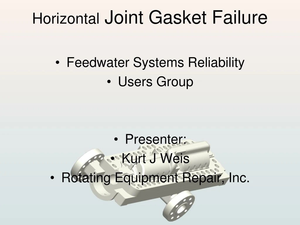
Horizontal Joint Gasket Failure • Feedwater Systems Reliability • Users Group • Presenter: • Kurt J Weis • Rotating Equipment Repair, Inc.
Finite Element AnalysisTo resolve split case gasket failure Ingersoll Rand 12 Stage Split Case Pump 4X10-12DAH-E
Equipment Analyzed • Ingersoll Rand 12 stage spilt case pump • 4X10-12DAH-E • 3000-3600psi operating range
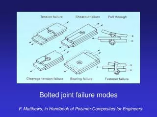
Previous Repair Solutions • Different Gasket materials • Increased Stud Preload (Use of “Super Studs”) • Beveled or Tapered Joint
Analyzing the Failure Mode • Gasket has minimal contact pressure between stages causing internal recirculation • Contact pressure can be analyzed with FEA • Accurate full casing model required to perform FEA
Creating Accurate Model • White Light Scanner/Digitizer gathered 3D point cloud data needed to create a model.
Creating Model • Using point cloud data, a Pro-E solid model-assembly was created.
Model Constraints • CA6NM Material, a 400 series stainless steel cast material • Feet restricted to horizontal movement only • Internal pressures
Analysis 1 • Standard Casing, 75% stud preload, (original design) to establish baseline.
Analysis 2 • Standard Casing, 112% stud preload
Analysis 3 • Beveled or Tapered Casing, 75% Stud Preload
Analysis 4 • Additional Row of studs, 75% Stud Preload
Analysis 5 • Additional Row of studs and beveled joint, 75% Stud Preload
The final design choice: Additional row of studs with no joint bevel
Results • Three pumps rebuilt with this modification. No pumps have been removed from service yet. • First installed pump has over 17000 hours on it, with no degradation in performance.
Reverse Engineering • The same technology can be used for reverse engineering impellers
Large Horizontal Circ Pump Impeller • Impeller was scanned and modeled using same technologies