Download
1 / 35
360 likes | 742 Views
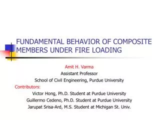
FUNDAMENTAL BEHAVIOR OF CFT BEAM-COLUMNS UNDER FIRE LOADING. Amit H. Varma, Sandgo Hong Purdue University 2005 ASCE Structures Congress New York City, NY. INTRODUCTION. Significant research has been conducted on the fire resistance of composite CFT columns under standard fire loading.

E N D
FUNDAMENTAL BEHAVIOR OF CFT BEAM-COLUMNS UNDER FIRE LOADING Amit H. Varma, Sandgo Hong Purdue University 2005 ASCE Structures Congress New York City, NY
INTRODUCTION • Significant research has been conducted on the fire resistance of composite CFT columns under standard fire loading. • Researchers at NRC-Canada (Lie, Kodur, Irwin, etc.), China (Lin-Hai Han), and Japan (Sakumoto using FR steel) • Focus on the behavior of columns subjected to constant axial loads, end conditions, and ASTM E119 fire time-temperature loading • The results provide fire resistance rating (FRR) values and have been used to develop standard fire resistant design • They do not provide knowledge of the fundamental force-deformation-temperature behavior of the CFT column or the critical failure segments • Limited research has been conducted on the fundamental force-deformation-temperature behavior of composite CFT beam-columns under combined axial and flexural loads and elevated temperatures from fire loading
MOTIVATION • Why is it relevant? Four reasons • The section force-deformation-temperature (P-M-f-T) represents the fundamental behavior of CFT beam-columns and it can be used to investigate the effects of various geometric, material, and insulation parameters on fire resistance. • These P-M-f-T responses can be used to calibrate beam-column finite element models used to conduct structural analysis under fire loading • The behavior and stability of moment resisting frames under fire loading depends on the strength interaction P-M-T curve for and the fire resistance of the connections • The stability of columns under fire loading also depends eventually on the P-M-f-T response of the critical failure segment at mid-span.
RESEARCH OBJECTIVES The objectives of this research project are: • To analytically and experimentally investigate the fundamental force-deformation-temperature (P-M-f-T) behavior of CFT beam-columns under elevated temperatures from fire loading. • To evaluate the effects of various material (concrete strength, steel yield stress), geometric (column size, width-to-thickness ratio), and insulation (thickness, thermal conductivity) on the fundamental P-M-f-T behavior of CFT beam-columns. • To develop (or calibrate) fiber-based finite element models for modeling CFT columns and beam-columns while investigating the fire behavior of CFT structures.
RESEARCH APPROACH • Development and validation of analytical approach for simulating the thermal and structural behavior of CFT members under structural loads and fire loading. • Preliminary analytical investigations of the fundamental P-M-f-T behavior of CFT beam-columns under elevated temperatures from fire loading. Evaluate the effects of geometric, material, and insulation parameters. • Experimental investigations to measure the fundamental P-M-f-T behavior of CFT beam-columns under combined axial and flexural loads and elevated temperatures from fire loading. • Analytical model calibration. The experimental results will be used to validate (or calibrate) the preliminary analytical models. The experimental results and calibrated models will be used to develop beam-column finite element models .
Step 3 Nonlinear Stress Analysis Step 1 Fire Dynamics Analysis Step 2 Nonlinear Heat Transfer Analysis ANALYTICAL APPROACH • The analytical approach was developed and validated using existing experimental data for CFT columns tested under fire loading by researchers at NRC, China, and Japan. • Development and validation of the analytical approach was presented in detail at the 2004 ASCE Structures Congress • The approach consists of three sequentially coupled analysis steps, where the results from each step are required to continue the analysis in the subsequent step: • Step I – Fire dynamics analysis • Step II – Nonlinear heat transfer analysis • Step III – Nonlinear stress analysis
Step 1 - FIRE DYNAMICS ANALYSIS • Fire dynamics analysis is conducted to simulate the convection and radiation heat transfer from the fire source (or furnace walls) to the structural component by solving the simplified Navier-Stokes equations numerically. • It is conducted using the NIST-BFRL developed software FDS, and the results include the heat flux incident upon the surfaces of the component or the surface T-t curves.
Step 2 - NONLINEAR HEAT TRANSFER ANALYSIS • Nonlinear heat transfer analysis is conducted to simulate the heat transfer through the cross-section of the component and along its length (and the associated convection and radiation losses). • The surface heat flux or T-t curves from the fire dynamics analysis serve as thermal loading for conducting the heat transfer analysis. • The heat transfer analysis can be conducted using the FDM or FEM. It is assumed uncoupled from the stress analysis, which is adequate for structural materials. • We used FEM because it links more easily with step 3. The results from the heat transfer analysis include the T-t curves for the nodes of the FEM mesh and thermal contours.
Step 3 – NONLINEAR STRESS ANALYSIS • Nonlinear stress analysis is conducted to determine the structural response of the component under applied structural and thermal loads. • The nodal time-temperature (T-t) curves obtained from the heat transfer analysis of step 2 define the thermal loads for the nonlinear stress analysis • The stress analysis can be conducted using the finite element method while using identical meshes for both steps 2 and 3. • The results from the analysis include the complete structural response: deflections, strains, stresses, load-displacement-temperature relationships.
300 mm CFT 250 mm CFT 200 mm CFT 350x 350x 7.7mm CFT Fy=285; f’c=19 MPa L=3.8 m; P/Po=50% SFRM Insulation 300x 300x 9mm CFT Fy=360; f’c=37 MPa L=3.5 m; P/Po=20% FR steel, Ceramic 200x 200x 6.35mm CFT Fy=350; f’c=47 MPa L=3.8 m; P/Po=15% Step 3 – NONLINEAR STRESS ANALYSIS • For example, the behavior of CFT columns tested according to the ASTM E119 was investigated using the 3-step approach • The sequentially coupled heat transfer and structural analysis were conducted using the FEM and option in ABAQUS. • The analytical approach was validated for an assortment of CFT columns with different material, geometric, insulation parameters tested independently by researchers in Canada, China, and Japan
GENERAL FINDINGS • The analytical approach was developed and validated, but the behavior of CFT columns under fire loading were found to be very sensitive with respect to: • Temperature dependent steel and concrete material structural properties, which are not measured or reported explicitly for most CFT specimens. • Column end conditions (rotational and axial restraint). End conditions obtained in the experiment may vary from those assumed in the analysis. • Variations in axial load level (P/Po). Axial load level can vary due to changes in axial load P due to restraint, or due to Po which depends on steel and concrete strength variation. • Relative motion (slip) between steel tube and concrete infill at ends. This slip occurs for some columns that were tested individually and the slip was allowed to occur. This may not be realistic.
PRELIMINARY ANALYTICAL INVESTIGATIONS • Preliminary investigations were conducted using the (developed and validated) analytical approach to determine the more fundamental force-deformation (P-M-f) behavior of CFT sections under elevated temperatures from fire loading. • These P-M-f-T responses and the effects of various material, geometric, and insulations parameters are the focus of the research for reasons explained earlier. • CFT parameters: • Width b = 200 or 300 mm. • Width-to-thickness ratio = 32 or 48 • Steel tube A500 Gr. B (300 MPa) • Concrete strength (f’c=35 MPa) • Axial load levels (P=0, 20%, 40%) • Thermal insulation thickness (0, 7.5, 13 mm thick)
PRELIMINARY ANALYTICAL INVESTIGATIONS • The analytical investigations were conducted on a segment of the CFT beam-columns. The length of the segment was equal to the cross-section width b. • It represents the critical segment of CFT column or beam-column subjected to axial and flexural loads and elevated temperatures from fire loading. Step 1 – FDS analysis to simulate heat transfer to the surface of the segment Step 2 – Nonlinear heat transfer analysis to simulate transfer through section and along length Step 3 – Nonlinear stress analysis for constant axial load, monotonic flexural loading moment), and nodal thermal loading (T-t) from step 2 Steps 2 and 3 conducted using the finite element method and ABAQUS
400oC 500oC 600oC 700oC 800oC MATERIAL PROPERTIES – T Dependent • Temperature dependent thermal and structural material properties were used along with the 3D finite element models of the CFT failure segment. • These material properties were based on values generally reported in the literature (Lie and Irwin 1995 etc.). • T-Thermal properties are given in a table in the paper 100oC Concrete s-e-T Steel s-e-T T=100oC 300oC T=300oC 500oC T=500oC 700oC T=700oC 900oC T=900oC
Step 2 – Results from heat transfer analysis Step 1 – Results from FDS Analysis for ASTM E119 T-t curve Surface Temperature =600oC Time = 14.2 mts. Surface Temperature =300oC Time = 5.6 mts. Thermal response- CFT without insulation
P/Po=20%, T=20oC P/Po=0%, T=20oC P/Po=20%, T=300oC P/Po=0%, T=300oC P/Po=20%, T=600oC P/Po=0%, T=600oC P/Po=20%, T=900oC P/Po=0%, T=900oC 7.5E-5 12.5E-5 2.5E-5 10.0E-5 5.0E-5 Structural Response – CFT without ins. Step 3 – P-M-f-T curves for CFT without insulation
Findings for CFTs Without Insulation • For CFTs without insulation: • Fire loading results in quick heating of the steel tube (broiling) while the concrete infill remains relatively cooler. Significant portions remain at T< 100oC till much later • This relative heating causes rapid reduction in flexural stiffness and strength of the CFT section under fire loading effects • This reduction depends primarily on the rise in steel temperature, and is independent of axial load level, width, and other parameters • This by itself, may not be a cause of concern unless the demands placed on the CFT without insulation exceed the reduced stiffness and strength at elevated temperatures
Steel surface w/o insulation Steel surface with insulation Insulation thick = 13.0 mm Time=180 mts Insulation thick = 6.5 mm Time=180 mts The heating of the composite CFT section becomes more uniform (not broiling) Thermal response of CFT with insulation • Consider similar CFTs with some insulation. Assume commonly used insulation materials with properties given in the paper. • The presence of thermal insulation results in a slow increase in the steel surface temperature.
P-M-f-T curves for CFT with b/t=32 P-M-f-T curves for CFT with b/t=48 Normalized Strength P-M Interaction Ambient T=20oC T=20oC Ins=6.5 mm Ins=13 mm P/Po=20% P/Po=0 P/Po=40% P/Po=20% Ambient T=20oC Ins. Thick = 13 mm P/Po=0 Ins. Thick = 6.5 mm Ins. Thick = 6.5 mm P/Po=20% b=200 mm, b/t=32 P/Po=0 Ins. Thick = 13 mm P/Po=40% P/Po=20% P/Po=40% P/Po=20% b=200 mm, b/t=48 P/Po=0 P/Po=40% P/Po=0 P/Po=20% b=300 mm, b/t=32 P/Po=40% P/Po=0 P/Po=40% 12.5E-5 12.5E-5 2.5E-5 2.5E-5 10.0E-5 10.0E-5 5.0E-5 5.0E-5 7.5E-5 7.5E-5 Curvature (1/mm) Curvature (1/mm) Structural Response of CFT with Insulation
Findings for CFTs with Insulation • The insulation thickness becomes the most important parameter influencing P-M-f-T behavior and strength (P-M) under elevated temperatures from fire loading. • As expected, CFTs with b/t =48 have greater increase in moment capacity with increase in axial load (below the balance point). This continues to be true at elevated temperatures also. • The tube width (b) and width-to-thickness (b/t) ratio do not have significant influence on the P-M-f-T behavior of CFTs at elevated temperatures from fire loading
EXPERIMENTAL INVESTIGATIONS • Experimental investigations will focus on measuring the P-M-f-T response of CFT segments. Parameters included in the experimental studies are: • Tube width (b) and b/t ratio • Concrete strength f’c • Axial load level • Heating (surface temperature) • Insulation thickness and type • Experimental test matrix is currently being finalized using results of preliminary investigations
CFT TEST SETUP • The test-setup will be similar to those used for measuring P-M-f response of beam-column specimens at ambient temperature • It will be a cantilever column with axial force and lateral load applied at the top (free) end and the bottom end clamped. A custom-built portable furnace will be placed to surround the plastic hinge region. It will subject the surface to the selected T-t curve. • Thus, the specimen plastic hinge region will be subjected to P, M, and T. • The deformations of the plastic hinge region will be measured using close-range photogrammetry and digital image processing techniques.
FURNACE DESCRIPTION • The portable furnace consists of ceramic fiber radiant heaters. Four such panel heaters are assembled to form a box around the hinge region. • Heaters have wattage density of 2.5 kW/ft2. Can provide surface temperature approaching 1200oC. They use radiant heating which is efficient and economic
FURNACE T-t CONTROL • Radiant heaters are fully controllable. Specify control surface T-t curve and the heater will provide it. • For example, in the experiment below, we are controlling steel surface T-t curve under the insulation. • The insulation surface T-t curve can also be directly controlled. This experiment is in progress.
FURNACE T-t CONTROL • In this experiment we are directly controlling the steel surface T-t curve without insulation to follow the ASTM E119 gas T-t curve.
DEFORMATION MEASUREMENTS • The deformation (or movement) of any point on the specimen surface can be measured using close-range photogrammetry and digital image processing fundamentals. • For example, the thermal expansion was measured as shown below.
TEMPERATURE MEASUREMENTS • Thermocouples bonded to steel and embedded in concrete to measure temperatures
EXPERIMENTAL INVESTIGATIONS • Will be conducted this year. Results to be presented at next ASCE Structures Congress. • Acknowledgments • National Science Foundation - funding • Purdue University • Dr. Jim Bethel – photogrammetry • Jarupat Srisa-Ard - student
MOTIVATION 2 • Researchers around the world have developed finite element method based computer programs to conduct structural analysis under fire loading. • For example, researchers at Liege Univ. (SAFIR), Sheffield Univ. (FEMFAN), Univ. of Manchester, Nat. Univ. of Singapore (SINTEF) • Most of these programs use fiber-based or concentrated hinge based beam-column finite elements for modeling the behavior of columns and beam-columns under fire loading • These finite elements must be validated (or calibrated) using experimental data and realistic P-M-f-T behavior
1.0 0.8 Section P-M at ambient 0.6 0.25 in. insulation after 180 mts. Nomalized axial capacity P/PY 0.4 No insulation after 35 mts. No Insulation after 15 mts. 0.5 in. insulation after 180 mts. 0.2 0 1.25 0 0.50 0.75 0.25 1.0 Nomalized moment capacity Mn/Mp MOTIVATION 3 • Consider a 6-story structure with perimeter moment resisting frames for lateral stiffness and stability. • Design for dead, live, wind loads. • Satisfy building and interstory drift requirements. • Consider state when subjected to D+0.5L+W+Compartment Fire load
P P M=P d P P MOTIVATION 4 • The behavior and failure of columns under constant axial load and elevated temperatures from fire loading also depends on the section P-M-f-T response of the failure segment.
ASTM E119 FDS Experiment FDM Step 1 - FIRE DYNAMICS ANALYSIS • During experiments, the furnace gas temperature was controlled to follow the ASTM E119 T-t curve. The temperatures of the CFT column surfaces were measured using thermocouples. • FDS model of the furnace, and the surface T-t curves for 200, 250, and 300 mm CFT columns that were tested shown below.
Step 2 - NONLINEAR HEAT TRANSFER ANALYSIS • For example, nonlinear heat transfer analyses of CFT columns tested by other researchers were conducted. • The surface T-t curves from step 1 were used as thermal loading • 3D finite element models were developed to conduct the heat transfer analysis and analyzed using ABAQUS. • The results were compared with experimental results.
Steel tube longitudinal strain Steel tube longitudinal stress (Pa) Concrete longitudinal strain Concrete longitudinal stress (Pa) Stress analysis results for CFT beam-column with b/t=32, P/Po = 20%, and insulation thickness=6.5 mm (Curvature = 12.5 x 10⁻⁵ 1/mm)