Beam-Columns
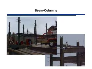
Beam-Columns. A. B. P 1. C. D. P 2. E. F. Members Under Combined Forces. Most beams and columns are subjected to some degree of both bending and axial load. e.g. Statically Indeterminate Structures. Interaction Formulas for Combined Forces. e.g. LRFD

Beam-Columns
E N D
Presentation Transcript
A B P1 C D P2 E F Members Under Combined Forces Most beams and columns are subjected to some degree of both bending and axial load e.g. Statically Indeterminate Structures
Interaction Formulas for Combined Forces e.g. LRFD If more than one resistance is involved consider interaction
Basis for Interaction Formulas Tension/Compression & Single Axis Bending Tension/Compression & Biaxial Bending Quite conservative when compared to actual ultimate strengths especially for wide flange shapes with bending about minor axis
AISC Interaction Formula – CHAPTER H AISC Curve r = required strength c = available strength
REQUIRED CAPACITY Pr Pc Mrx Mcx Mry Mcy
Axial Capacity Pc Elastic Buckling Stress corresponding to the controlling mode of failure (flexural, torsional or flexural torsional) Fe: Theory of Elastic Stability (Timoshenko & Gere 1961) Flexural Buckling Torsional Buckling 2-axis of symmetry Flexural Torsional Buckling 1 axis of symmetry Flexural Torsional Buckling No axis of symmetry AISC Eqtn E4-4 AISC Eqtn E4-5 AISC Eqtn E4-6
Effective Length Factor Free to rotate and translate Fixed on top Free to rotate Fixed on bottom Fixed on bottom Fixed on bottom
Ic Lc Ig Lg Ig Lg A Ic Lc B Effective Length of Columns • Assumptions • All columns under consideration reach buckling Simultaneously • All joints are rigid • Consider members lying in the plane of buckling • All members have constant A Define:
Effective Length of Columns Use alignment charts (Structural Stability Research Council SSRC) LRFD Commentary Figure C-C2.2 p 16.1-241,242 • Connections to foundations • (a) Hinge • G is infinite - Use G=10 • (b) Fixed • G=0 - Use G=1.0
Axial Capacity Pc LRFD
Moment Capacity Mcx or Mcy REMEMBER TO CHECK FOR NON-COMPACT SHAPES
Moment Capacity Mcx or Mcy REMEMBER TO ACCOUNT FOR LOCAL BUCKLING IF APPROPRIATE
Moment Capacity Mcx or Mcy LRFD ASD
Axial Demand Pr LRFD ASD factored service
P y M Second Order Effects & Moment Amplification P W ymax @ x=L/2 = d Mmax @ x=L/2 = Mo + Pd = wL2/8 + Pd additional moment causes additional deflection
additional moment causes additional deflection Second Order Effects & Moment Amplification Consider Mmax = Mo + PD
Second Order Effects & Moment Amplification • Total Deflection cannot be Found Directly • Additional Moment Because of Deformed Shape • First Order Analysis • Undeformed Shape - No secondary moments • Second Order Analysis (P-d and P-D) • Calculates Total deflections and secondary moments • Iterative numerical techniques • Not practical for manual calculations • Implemented with computer programs
Design Codes AISC Permits Second Order Analysis or Moment Amplification Method Compute moments from 1st order analysis Multiply by amplification factor
Derivation of Moment Amplification Moment Curvature P M 2nd order nonhomogeneous DE
Derivation of Moment Amplification Boundary Conditions Solution
Derivation of Moment Amplification Solve for B
Derivation of Moment Amplification Deflected Shape
Derivation of Moment Amplification Moment Mo(x) Amplification Factor
Braced vs. Unbraced Frames Eq. C2-1a
Braced vs. Unbraced Frames Eq. C2-1a Mnt = Maximum 1st order moment assuming no sidesway occurs Mlt = Maximum 1st order moment caused by sidesway B1 = Amplification factor for moments in member with no sidesway B2 = Amplification factor for moments in member resulting from sidesway
Braced Frames Pr = required axial compressive strength = Pu for LRFD = Pa for ASD Pr has a contribution from the PD effect and is given by
Braced Frames a = 1 for LRFD = 1.6 for ASD
Braced Frames Cm coefficient accounts for the shape of the moment diagram
Braced Frames Cm For Braced & NO TRANSVERSE LOADS M1: Absolute smallest End Moment M2: Absolute largest End Moment
Braced Frames Cm For Braced & NO TRANSVERSE LOADS COSERVATIVELY Cm= 1
Unbraced Frames Eq. C2-1a Mnt = Maximum 1st order moment assuming no sidesway occurs Mlt = Maximum 1st order moment caused by sidesway B1 = Amplification factor for moments in member with no sidesway B2 = Amplification factor for moments in member resulting from sidesway
Unbraced Frames a = 1.00 for LRFD = 1.60 for ASD = sum of required load capacities for all columns in the story under consideration = sum of the Euler loads for all columns in the story under consideration
Unbraced Frames Used when shape is known e.g. check of adequacy Used when shape is NOT known e.g. design of members
Unbraced Frames I = Moment of inertia about axis of bending K2 = Unbraced length factor corresponding to the unbraced condition L = Story Height Rm = 0.85 for unbraced frames DH = drift of story under consideration SH = sum of all horizontal forces causing DH