Download
1 / 39
430 likes | 1.2k Views
Energy and Exergy Analysis of Diesel Engine Powered Cogeneration Systems. Ayşegül Abuşoğlu Mehmet Kanoğlu Mechanical Engineering Department University of Gaziantep Summer Course on Exergy and Its Applications 28-30 June 2009 Suleyman Demirel University, Isparta , Turkey.

E N D
Energy and Exergy Analysis of Diesel Engine Powered Cogeneration Systems Ayşegül Abuşoğlu MehmetKanoğlu Mechanical Engineering Department University of Gaziantep Summer Course on Exergy and Its Applications 28-30 June 2009 SuleymanDemirel University, Isparta, Turkey
İKİNCİ YASA VE EKSERJİ ANALİZİ • Termodinamik bilimi iki temel doğal yasaya dayanır: Birinci yasa ve ikinci yasa. • Termodinamiğin birinci yasası, enerjinin korunumunu ifade eder ve enerji dönüşümleri sırasında enerjinin bir şekilden diğerine dönüşebileceğini fakat toplam enerjinin sabit kalacağını ifade eder. • Termodinamiğin ikinci yasası, enerjinin kalitesi olduğunu ve gerçek hal değişimlerinin enerji kalitesinin azalması yönünde olacağını ifade eder. • Enerjinin kalitesini veya iş yapma potansiyelini sayısal olarak ifade etme çabaları ekserji adı verilen bir özelliğin tanımlanmasını sağlamıştır. • Ekserji, enerjinin işe çevrilebilme potansiyeli olarak tanımlanır ve bir kaynaktan elde edilebilecek maksimum işi ifade eder. • Bir hal değişimi sırasında kaybedilen iş potansiyeli tersinmezlik veya ekserji kaybı olarak tanımlanır.
Bir hal değişimi sırasında ekserji kayıpları ne kadar az ise üretilen iş o kadar fazladır veya tüketilen iş o kadar azdır. • Bir sistemin performansı ekserji kayıplarının en aza indirgenmesi yoluyla maksimize edilebilir. • Ekserji analizi, ikinci yasaya dayanan bir termodinamik analiz olup enerji sistemlerini ve hal değişimlerini gerçekçi ve anlamlı biçimde değerlendirmeyi ve karşılaştırmayı mümkün kılar. • Ekserji analizi ile bulunan ekserji veya ikinci yasa verimleri gerçek sistem performansını maksimum performansla karşılaştırırken, ekserji analizi yardımıyla termodinamik kayıpların yerleri, miktarları ve nedenleri bulunabilir. • Ekserji analizi sonuçları sistem performansının iyileştirilmesinde ve daha iyi tasarımların yapılmasında kullanılır.
EKSERJİ NEDİR? Ekserji:Bir sistemin verilen bir durumda sahip olduğu kullanılabilir iş potansiyeli. Ekserji, bir sistemin herhangi bir termodinamik yasaya aykırı olmaksızın sağlayabileceği maksimum işi ifade eder. Atmosferde çok büyük miktarda enerji varken, ekserjisi sıfırdır.
Kullanılamayan enerji Toplam enerji Ekserji Enerjinin sadece bir bölümü işe çevrilebilir. Geriye kalan bölümü tersinir bir ısı makinası yardımıyla bile işe dönüştürülemez.
Isı makinaları İş üreten sistemler İş tüketen sistemler Soğutma makinaları ve ısı pompaları İKİNCİ YASA veya EKSERJİ VERİMİ, II Aynı ısıl verime fakat farklı maksimum ısıl verime sahip iki ısı makinası. İkinci yasa verimi bir sistemin gerçek veriminin tersinir şartlardaki verime olan oranının bir ölçüsüdür.
Isı transferi Sıcak su, 80C Atmosfer25C Ekserji veriminin genel tanımı Doğal olarak meydana gelen işlemlerin ikinci yasa verimleri sıfırdır (iş potansiyeli değerlendirilmiyorsa). Bütün tersinir sistemlerin ikinci yasa verimleri % 100’dür.
Çevre Tersinmez proses Tersinir proses İmkansız proses Sistem Ekserji Yıkımı Ekserji yıkımı gerçek işlemler için pozitif, tersinir işlemler için sıfırdır. Ekserji yıkımı kaybedilen iş potansiyelini ifade eder vetersinmezlikveyakayıp iş olarak da isimlendirilir. Bir sistemin ekserji değişimi negatif olabilir ama ekserji yıkımı olamaz.
İKİNCİ YASA VE EKSERJİNİN TEMEL KULLANIM ALANLARI • İşlemlerin yönü tayin edilebilir. • İkinci yasa enerjinin miktarı kadar kalitesi olduğunu da ifade eder. Birinci yasa enerjinin miktarıyla ilgilidir ve enerjinin bir halden diğerine dönüşümüyle ilgilenirken enerjinin kalitesiyle ilgilenmez. • İkinci yasa ile enerjinin kalitesi sayısal olarak ifade edilirken işlemler sırasında enerjinin kalitesindeki azalmayı bulmamızı sağlar. • İkinci yasa ile yaygın olarak kullanılan mühendislik sistemlerinin teorik üst limit performansı bulunur. • Ekserji verimi ile gerçek performansın ideal performansa ne kadar yakınlaştığı ve termodinamik kayıpların miktar, neden ve yerleri bulunur. • Ekserji analizi sistemlerin tasarım, optimizasyon ve geliştirilmesinde kullanılır.
Oda 25C 2C 2 kW Oda, 25C 2 kW 0.144 kW Tersinir ısı pompası Dış hava, 2C ÖRNEK: Bir odanın elektrikle ısıtılması Gerçek proses Tersinir proses
What is Cogeneration? • Cogenerationis the simultaneous generation of heat and power. • The principle behind cogeneration is simple: • Conventional power generation, on average, is only 35% efficient – up to 65% of the energy potential is released as waste heat. • Combined cycle generation can improve this to 55%. • Cogeneration reduces this loss by using the heat for industry, commerce and home heating/cooling.
The Benefits of Cogeneration • Increased efficiency of energy conversion and use • Lower emissions to the environment • Cost-effectiveness and reducing the need for waste disposal: Biomass fuels, some waste materials such as refinery gases, process or agricultural waste can be used as fuels. • Large cost savings, providing additional competitiveness for industrial and commercial users, and offering affordable heat for domestic users, • An opportunity to move towards more decentralised forms of electricity generation, • An opportunity to increase the diversity of generation plant, and provide competition in generation, • Increased employment: Development of cogeneration systems is a generator of jobs.
Cogeneration Technologies • Cogeneration plant consists of four basic elements: • A prime mover (engine) • An electricity generator • A heat recovery system • A control system • Currently available drive systems for cogeneration units include: • Steam turbines • Reciprocating engines • Gas turbines • Combined cycle • Fuel cells • Stirling engine • Micro – turbines
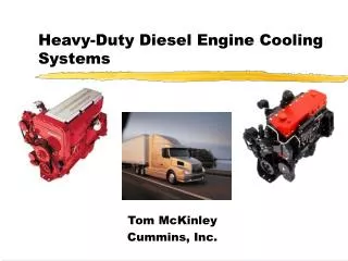
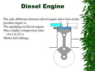
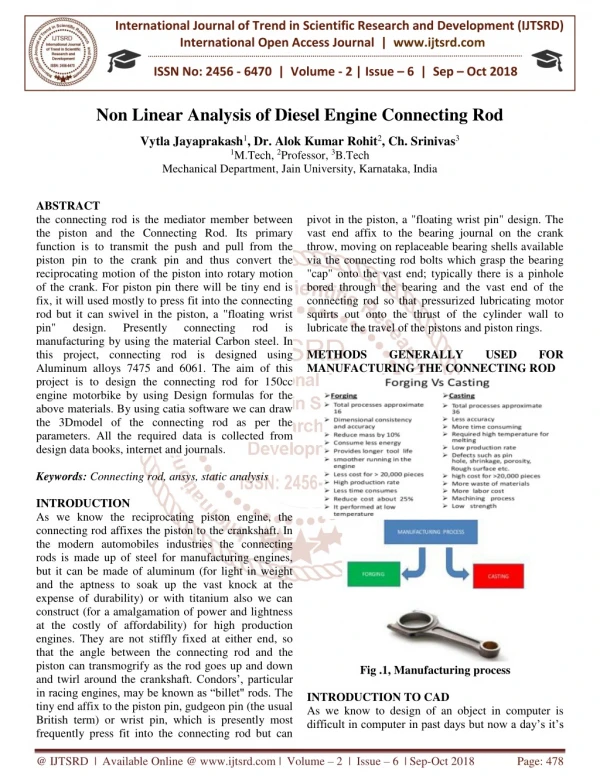
Reciprocating Engines • The reciprocating engines used in cogeneration are internal combustion engines operating on the same familiar principles as their petrol and diesel engine automotive counterparts, • Reciprocating engines give a higher electrical efficiency, but it is more difficult to use the thermal energy they produce, since it is generally at lower temperatures and is dispersed between exhaust gases and engine cooling systems, • There are two types of reciprocating engines, classified by their method of ignition: • Spark Ignition (SI) Engine • Compression Ignition (CI) Engine (DIESEL Engine).
Diesel Engine Powered Cogeneration • Diesel engines for large scale cogeneration are predominantly four-stroke direct injection engines fitted with turbochargers and intercoolers, • Diesel engines will accept gas oil, heavy fuel oil and natural gas (latter in duel fuel mode with a small quantity of gas oil), • Shaft efficiencies are 35-45%, and output range is up to 15 MW • Diesel engines up to 2 MWe are derivated from original automative diesel operating on gas oil, and from 2 MWe to 20 MWe evolved from marine diesels operating on dual fuel or residual fuels running at medium to low speed.
SANKO Diesel Engine Powered Cogeneration (DEPC) • The Diesel Engine Cogeneration Plant (SANKO Energy) has a total installed electricity and steam generation capacities of 25.32 MW and 8.1 tons/hr respectively. • The electricity is generated by three, diesel engine actuated generator sets each having two turbochargers. • The engine is four stroke compression ignition engine with 18 cylinders in a V configuration. • Heavy fuel oil is used as fuel for engines. • The permissible annual electricity production is 217 GWh and the annual fuel consumption is nearly 45000 tons at designed operating conditions.
The Schematic of The Actual Diesel Engine Powered Cogeneration
Plant data, thermodynamic properties, and exergies in the DEPC plant wrt state points in the schematic
The Governing Laws for Energy and Exergy • Steady flow conditions can be closely approximated bydevices that are intended for continuous operation such as turbines, pumps, boilers, condensers and heat exchangers of diesel power plants. • The governing equations below can be used for these and similar devices once the transient start-up period is completed and a steady operation is established.
Mass, energy, and exergy balances for any control volume at steady state with negligible kinetic and potential energy changes can be expressed respectively by the equations;
The net exergy transfer by heat at temperature T, whichis given by • The specific flow exergy and the rate of total exergy are given by
The isentropic efficiencies of turbine generally range from 80 to 90% where as the isentropic efficiencies of compressor range from 70 to 85%. • The second-law (exergy) efficiency of a turbine can be defined as a measure of how well the stream availability of the fluid is converted into shaft-work output as
The second law efficiency of the compressor is defined similarly as • The second law-efficiency of the heat exchangers in the power plant is measured by the increase in the exergy of the cold stream divided by the decrease in the exergy of the hot stream,
The exergy destruction in a component is calculated from the exergy balance as • The rate of exergy destruction in a system for the kth component can be compared to the exergy rate of the fuel provided to the overall system
Alternatively, the component exergy destruction rate can be compared to the total exergy destruction rate within the system • The exergy loss ratio is defined similarly by comparing the exergy loss to the exergy of the fuel provided to the overall system
The First Law Efficiency of DEPC • The first law thermal efficiency of the overall DEPC plant is obtained from the ratio of the sum of the net electrical power and steam outputs to the heat input of the sum of heavy fuel oil and fresh treated water at corresponding states
The Second Law Efficiency of DEPC • The exergetic efficiency of the DECGS, based on the chemical exergy input of the fuel oil and total exergy destructions of the components in the plant
The Second Law Efficiency of Diesel Engine (1st Approach) • Exergetic efficiency of diesel engine may be obtained by using two different approaches. The first approach is given such as
The Second Law Efficiency of Diesel Engine (2nd Approach) • The second approach in the definition of the exergetic efficiency is that: the main purpose of the diesel engine is the production of electricity and the main exergy supplied comes from fuel. Thus the alternative definition may be written as
Energetic and Exergetic Analyses Results for the Sub-systems in the DEPC Plant
The Rate of ExergyDestructions of theComponents in the DEPC Plant
Variation of Fuel Utilization Efficiency (FUE) and Power to Heat Ratio (PHR) as a Function of Process Steam Output for DEPC
Concluding Remarks • The total exergy input of fuel by considering three diesel engine systems to DEPC plant is62,757 kW. • 40.4% of exergy entering the plant is converted to electrical power and 5% of this power is used for parasitic load in the plant to drive auxiliary components in the plant. • The net steam production of the plant represents only 0.3% of the total exergy input. The remaining 59.3% of the exergy input is destroyed.This corresponds to 37,246 kW, which is the total exergy destruction in the plant.
The exergetic efficiency of the plant is determined to be 40.6%. • The exergy destruction in the diesel engines of the cogeneration plant accounts about 46.0% of the total exergy input and 81.4% of the total exergy destruction in the plant. • The exergy destruction in the engine is mostly due to the highly irreversible combustion process, heat losses from the engine and friction. • The exergetic efficiencies of the compressor and turbine of the turbocharger are 82.6% and 88.1%, respectively. These values indicate sufficient exergetic performance from the turbocharger.
The exergetic efficiencies of the waste heat boiler and condenser are calculated as 11.4% and 16.6%, respectively making them the least efficient components of the plant. • The intercooler has an exergetic efficiency of 26.3%. Exergy destructions in these heat exchange units in the plant are mainly due to the high average temperature difference between the two unmixed fluid streams. • The percent of exergy loss associated with lubrication oil cooler is low. This is due to the cooling of lubrication oil by using low-temperature water.