Download
1 / 61
610 likes | 840 Views
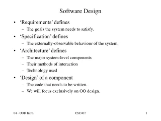
With a focus on OO design techniques. Software Design. Software Engineering Process activities. Software specification Software design and implementation Software validation Software evolution. Software design and implementation.

E N D
With a focus on OO design techniques Software Design
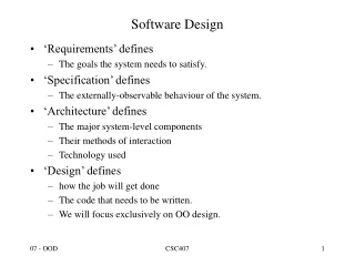
Software Engineering Process activities • Software specification • Software design and implementation • Software validation • Software evolution
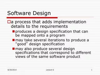
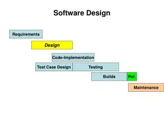
Software design and implementation • The process of converting the system specification into an executable system. • Software design • Design a software structure that realises the specification; • Implementation • Translate this structure into an executable program; • The activities of design and implementation are closely related and may be inter-leaved.
Design process activities • Architectural design • Abstract specification • Interface design • Component design • Data structure design • Algorithm design
Structured methods • Systematic approaches to developing a software design. • The design is usually documented as a set of graphical models. • Possible models • Object model; • Sequence model; • State transition model; • Structural model; • Data-flow model.
Object-oriented Design Designing systems using self-contained objects and object classes
Objectives • To explain how a software design may be represented as a set of interacting objects that manage their own state and operations • To describe the activities in the object-oriented design process • To introduce various models that describe an object-oriented design • To show how the UML may be used to represent these models
Topics covered • Objects and object classes • An object-oriented design process • Design evolution
Characteristics of OOD • Objects are abstractions of real-world or system entities and manage themselves • Objects are independent and encapsulate state and representation information. • System functionality is expressed in terms of object services • Shared data areas are eliminated. Objects communicate by message passing • Objects may be distributed and may execute sequentially or in parallel
Advantages of OOD • Easier maintenance. Objects may be understood as stand-alone entities • Objects are appropriate reusable components • For some systems, there may be an obvious mapping from real world entities to system objects
Object-oriented development • Object-oriented analysis, design and programming are related but distinct • OOA is concerned with developing an object model of the application domain • OOD is concerned with developing an object-oriented system model to implement requirements • OOP is concerned with realising an OOD using an OO programming language such as Java or C++
Objects and object classes • Objects are entities in a software system which represent instances of real-world and system entities • Object classes are templates for objects. They may be used to create objects • Object classes may inherit attributes and services from other object classes
Objects An object is an entity which has a state and a defined set of operations which operate on that state. The state is represented as a set of object attributes. The operations associated with the object provide services to other objects (clients) which request these services when some computation is required. Objects are created according to some object class definition. An object class definition serves as a template for objects. It includes declarations of all the attributes and services which should be associated with an object of that class.
The Unified Modeling Language • Several different notations for describing object-oriented designs were proposed in the 1980s and 1990s • The Unified Modeling Language is an integration of these notations • It describes notations for a number of different models that may be produced during OO analysis and design • It is now a de facto standard for OO modelling
Object communication • Conceptually, objects communicate by message passing. • Messages • The name of the service requested by the calling object. • Copies of the information required to execute the service and the name of a holder for the result of the service. • In practice, messages are often implemented by procedure calls • Name = procedure name. • Information = parameter list.
Message examples // Call a method associated with a buffer // object that returns the next value // in the buffer v = circularBuffer.Get () ; // Call the method associated with a// thermostat object that sets the // temperature to be maintained thermostat.setTemp (20) ;
Generalisation and inheritance • Objects are members of classes which define attribute types and operations • Classes may be arranged in a class hierarchy where one class (a super-class) is a generalisation of one or more other classes (sub-classes) • A sub-class inherits the attributes and operations from its super class and may add new methods or attributes of its own • Generalisation in the UML is implemented as inheritance in OO programming languages
Advantages of inheritance • It is an abstraction mechanism which may be used to classify entities • It is a reuse mechanism at both the design and the programming level • The inheritance graph is a source of organisational knowledge about domains and systems
Problems with inheritance • Object classes are not self-contained. they cannot be understood without reference to their super-classes • Designers have a tendency to reuse the inheritance graph created during analysis. Can lead to significant inefficiency • The inheritance graphs of analysis, design and implementation have different functions and should be separately maintained
Inheritance and OOD • There are differing views as to whether inheritance is fundamental to OOD. • View 1. Identifying the inheritance hierarchy or network is a fundamental part of object-oriented design. Obviously this can only be implemented using an OOPL. • View 2. Inheritance is a useful implementation concept which allows reuse of attribute and operation definitions. Identifying an inheritance hierarchy at the design stage places unnecessary restrictions on the implementation • Inheritance introduces complexity and this is undesirable, especially in critical systems
UML associations • Objects and object classes participate in relationships with other objects and object classes • In the UML, a generalised relationship is indicated by an association • Associations may be annotated with information that describes the association • Associations are general but may indicate that an attribute of an object is an associated object or that a method relies on an associated object
Concurrent objects • The nature of objects as self-contained entities make them suitable for concurrent implementation • The message-passing model of object communication can be implemented directly if objects are running on separate processors in a distributed system
Servers and active objects • Servers. • The object is implemented as a parallel process (server) with entry points corresponding to object operations. If no calls are made to it, the object suspends itself and waits for further requests for service • Active objects • Objects are implemented as parallel processes and the internal object state may be changed by the object itself and not simply by external calls
Active transponder object • Active objects may have their attributes modified by operations but may also update them autonomously using internal operations • Transponder object broadcasts an aircraft’s position. The position may be updated using a satellite positioning system. The object periodically update the position by triangulation from satellites
Java threads • Threads in Java are a simple construct for implementing concurrent objects • Threads must include a method called run() and this is started up by the Java run-time system • Active objects typically include an infinite loop so that they are always carrying out the computation
An object-oriented design process • Define the context and modes of use of the system • Design the system architecture • Identify the principal system objects • Develop design models • Specify object interfaces
Weather system description A weather data collection system is required to generate weather maps on a regular basis using data collected from remote, unattended weather stations and other data sources such as weather observers, balloons and satellites. Weather stations transmit their data to the area computer in response to a request from that machine. The area computer validates the collected data and integrates it with the data from different sources. The integrated data is archived and, using data from this archive and a digitised map database a set of local weather maps is created. Maps may be printed for distribution on a special-purpose map printer or may be displayed in a number of different formats.
Weather station description A weather station is a package of software controlled instruments which collects data, performs some data processing and transmits this data for further processing. The instruments include air and ground thermometers, an anemometer, a wind vane, a barometer and a rain gauge. Data is collected every five minutes. When a command is issued to transmit the weather data, the weather station processes and summarises the collected data. The summarised data is transmitted to the mapping computer when a request is received.
System context and models of use • Develop an understanding of the relationships between the software being designed and its external environment • System context • A static model that describes other systems in the environment. Use a subsystem model to show other systems. Following slide shows the systems around the weather station system. • Model of system use • A dynamic model that describes how the system interacts with its environment. Employs use-cases to show interactions
Architectural design • Once interactions between the system and its environment have been understood, you use this information for designing the system architecture • Layered architecture is appropriate for the weather station • Interface layer for handling communications • Data collection layer for managing instruments • Instruments layer for collecting data • Rule of thumb: there should be no more than 7 entities in an architectural model
Object identification • Identifying objects (or object classes) is the most difficult part of object oriented design • There is no 'magic formula' for object identification. It relies on the skill, experience and domain knowledge of system designers • Object identification is an iterative process. You are unlikely to get it right first time
Approaches to identification • Use a grammatical approach based on a natural language description of the system (used in Hood method) • http://www.esa.int/TEC/Software_engineering_and_standardisation/TECKLAUXBQE_0.html • Base the identification on tangible things in the application domain • Use a behavioural approach and identify objects based on what participates in what behaviour • Use a scenario-based analysis. The objects, attributes and methods in each scenario are identified
Weather station object classes • Ground thermometer, Anemometer, Barometer • Application domain objects that are ‘hardware’ objects related to the instruments in the system • Weather station • The basic interface of the weather station to its environment. It therefore reflects the interactions identified in the use-case model • Weather data • Encapsulates the summarised data from the instruments
Further objects and object refinement • Use domain knowledge to identify more objects and operations • Weather stations should have a unique identifier • Weather stations are remotely situated so instrument failures have to be reported automatically. Therefore attributes and operations for self-checking are required • Active or passive objects • In this case, objects are passive and collect data on request rather than autonomously. This introduces flexibility at the expense of controller processing time
Design models • Design models show the objects and object classes and relationships between these entities • Static models describe the static structure of the system in terms of object classes and relationships • Dynamic models describe the dynamic interactions between objects.
Examples of design models • Sub-system models that show logical groupings of objects into coherent subsystems • Sequence models that show the sequence of object interactions • State machine models that show how individual objects change their state in response to events • Other models include use-case models, aggregation models, generalisation models,etc.
Subsystem models • Shows how the design is organised into logically related groups of objects • In UML, these are shown using packages - an encapsulation construct. This is a logical model. The actual organisation of objects in the system may be different.