Download
1 / 46
480 likes | 682 Views
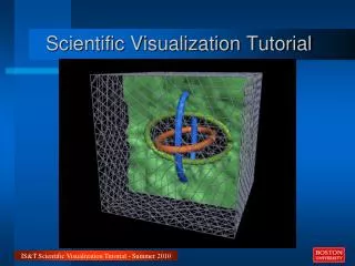
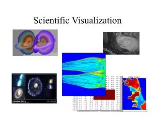
Envisioning Information Lecture 13 – Scientific Visualization Scalar 3D Data: Isosurfacing. Ken Brodlie kwb@comp.leeds.ac.uk. Scalar 3D Visualization. This is often called: Volume Visualization because data is defined in a volume. Major applications include: Medical imaging

E N D
Envisioning Information Lecture 13 – Scientific Visualization Scalar 3D Data: Isosurfacing Ken Brodlie kwb@comp.leeds.ac.uk ENV 2006
Scalar 3D Visualization • This is often called: Volume Visualization because data is defined in a volume. • Major applications include: • Medical imaging • Environmental science • Engineering – computational fluid dynamics • Main approaches are: • Slicing and Surface extraction (this morning) • Volume rendering (this afternoon) ENV 2006
Slicing and Surface Extraction • SLICING • Take a slice through the 3D volume (often orthogonal to one of the axes), reducing it to a 2D problem • See IRIS Explorer Slice module • ISOSURFACING • Extract a surface of constant value through the volume • See IRIS Explorer IsosurfaceLat module Note analogous techniques in 2D visualization: 1D cross-sections, and contours (=isolines) ENV 2006
Isosurface Examples ENV 2006
Notation vertex f111 f011 f001 f101 Volume of data voxel f010 f110 Each voxel transformed to unit cube f000 f100 ENV 2006
Data Enrichment – Nearest Neighbour Interpolation Value at any interior point taken as value at nearest vertex f111 f011 f001 Fast Discontinuous f101 f010 f110 f000 f100 ENV 2006
f111 f011 f001 f101 f010 f110 f000 f100 Data Enricment – Trilinear Interpolation The value at is found by: (i) 4 1D interpolations in x (ii) 2 1D interpolations in y (iii) 1 1D interpolation in z ENV 2006
Isosurfacing ENV 2006
Lobster – Increasing the Threshold Level ENV 2006 From University of Bonn
Because the surface is so complex we approximate by the triangles shown Accurate Isosurface of Trilinear Interpolant True isosurface of a trilinear interpolant is a curved surface cf contouring where contours are hyperbola ENV 2006
Isosurface Construction • For simplicity, we shall work with zero level isosurface, and denote positive vertices as There are EIGHT vertices, each can be positive or negative - so there are 28 = 256 different cases! ENV 2006
These two are easy… There is no portion of the isosurface inside the cube! ENV 2006
Isosurface Construction – One Positive Vertex Intersections with edges found by inverse linear interpolation ENV 2006 (as in contouring)
Isosurface Construction – One Positive Vertex Joining edge intersections across faces forms a triangle as part of the isosurface ENV 2006
Isosurface Construction - Positive Vertices at Opposite Corners ENV 2006
Isosurface Construction • One can work through all 256 cases in this way - although it quickly becomes apparent that many cases are similar. • For example: • 2 cases where all are positive, or all negative, give no isosurface • 16 cases where one vertex has opposite sign from all the rest • In fact, there are only 15 topologically distinct configurations ENV 2006
Canonical Cases for Isosurfacing The 256 possible configurations can be grouped into these 15 canonical cases on the basis of complementarity (swapping positive and negative) and rotational symmetry The advantage of doing this is for ease of implementation - we just need to code 15 cases not 256 ENV 2006
Isosurface Construction • In some configurations, just one triangle forms the isosurface • In other configurations ... • ...there can be several triangles • …or a polygon with 4, 5 or 6 points which can be triangulated • A software implementation will have separate code for each configuration • The classic algorithm is called Marching Cubes – find isosurface in one cube, then next and so on, marching from cube to cube ENV 2006
Isosurfacing by Marching Cubes Algorithm • Advantages • isosurfaces good for extracting boundary layers • surface defined as triangles in 3D - well-known rendering techniques available for lighting, shading and viewing ... with hardware support • Disadvantages • shows only a slice of data • ambiguities? ENV 2006
Ambiguities • Marching cubes suffers from exactly the same problems that we saw in contouring Case 3: Triangles are chosen to slice off the positive vertices - but could they have been drawn another way? ENV 2006
Marching Tetrahedra • As in contouring, another solution is to divide into simpler shapes - here they are tetrahedra 24 tetrahedra in all As in 2D case, this removes ambiguities… Cost is greater number of triangles which increases rendering time Value at centre = average of vertex values ENV 2006
A Rough Guide to Rendering ENV 2006
Rendering of Triangles • Surface views for 2D scalar visualization, and isosurfaces for 3D scalar visualization both generate a triangular mesh surface • Techniques for rendering these meshes rely on : • an understanding of how light is reflected from surfaces - to define the colour of points within each triangle • generating a 2D image representation of the 3D scene • Just a simplified view here... ENV 2006
Reflection Model • There are two major components to consider in modelling reflection of light from a surface • diffuse reflection: this gives a dull effect; light is scattered evenly and gives the colour of the surface • specular reflection: this gives shininess of surface; light is reflected at angle of perfect reflection and has colour of incoming light • total effect is sum of both (plus ambient light) ENV 2006
I = Kd (cos ) I* Reflection Model – Diffuse Reflection light source N L surface I* = Intensity of light source N = Surface normal L = Direction of light source Kd = Diffuse-reflection coefficient (gives colour) I = Reflected intensity * intensity of reflected light depends on angle of light to surface * equal reflection in all directions I, I*, Kd have R, G, B components ENV 2006
I = Ks( cos )n I* n varies with material large n : shiny small n : dull Reflection Model – Specular Reflection light source N R eye L V surface Intensity depends on angle between eye and reflected light ray - and type of material I* = Intensity of light source V = View direction R = Direction of perfect reflected light Ks = Specular-reflection coefficient I = Reflected intensity ENV 2006
Effect of Diffuse ReflectionSlide from Alan Watt, University of Sheffield ENV 2006
Effect of Diffuse plus Specular ReflectionSlide from Alan Watt, University of Sheffield ENV 2006
Rendering • To render a scene composed of a number of surfaces (here triangles)… • ..project the surfaceson to a viewing plane, determining which are visible to the eye, and assigning the colour as given by the lighting model ENV 2006
view plane Perspective Projection eye point ENV 2006
Parallel Projection direction of projection view plane ENV 2006
Triangle Rendering • Thus, by projecting the triangle vertices, we get position of triangle in image - how can we get the colour of pixels within the triangle? • There are two techniques of increasing complexity - and increasing realism: • Flat shading • Gouraud shading ENV 2006
Flat Shading of Triangular Mesh • Each point in a triangle given the same intensity N2 N1 Calculate intensity for each triangle from reflection model equations N4 N3 Fast and simple - but intensity discontinuities at edges ENV 2006
Gouraud Shading of Triangular Mesh • Aim is to shade mesh as though it were curved surface Step 1: Approximate normal at each vertex in some way - one possibility is to average the normals of surrounding triangles ENV 2006
Gouraud Shading of Triangular Mesh I1 Step 2: Calculate the intensity at each vertex using the lighting model I3 I2 I1 Step 3: Calculate the intensity at any interior point by linear interpolation in triangle I3 I2 ENV 2006
Comparison of Techniques • Flat shading: • fast and simple, 1 lighting calc’n done per triangle, all pixels given same intensity • discontinuity in intensity across edges • Gouraud shading • relatively fast, 1 lighting calc’n per vertex, intensity linearly interpolated from vertex intensities - giving smooth appearance – now industry standard ENV 2006
Constant or Flat Shading -Each Polygon has Constant Shade ENV 2006
Gouraud Shading ENV 2006
Flat and Gouraud ShadingSlides from Alan Watt, University of Sheffield ENV 2006
Rendering of Isosurfaces • Isosurface algorithms generate triangular meshes which can be rendered as just described • Key is the estimation of vertex normals for Gouraud shading • One possibility is to construct the entire surface, then assign vertex normals as average of normals of surrounding triangles ENV 2006
Rendering of Isosurfaces • An alternative - generally preferred - is based on fact that surface normal is equal to the gradient vector of f At (xi,yj,zk), df/dx = 0.5*(f i+1,j,k - f i-1,j,k) df/dy = 0.5*(f i,j+1,k - f i,j-1,k) df/dz = 0.5*(f i,j,k+1 - f i,j,k-1) This gives us normals at all grid points, and then trilinear interpolation will give normals at the triangle vertices ENV 2006
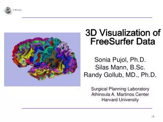
Example – brain visualization Note illumination of isosurface http://www.csit.fsu.edu/~futch/iso/ ENV 2006
Isosurfacing can be applied to rendering of objects… here an engine Example – mechanical engineering Computer Science, UC Davis ENV 2006
Vertebrae… .. Also from UC Davis Example – medical application ENV 2006
Classic paper: W.E. Lorensen and H.E. Cline, Marching Cubes : A High Resolution 3D Surface Reconstruction Algorithm. Computer Graphics, vol21, 4, pp163—169, 1987 Recent paper: A. Lopes and K. Brodlie, Improving the Robustness and Accuracy of the Marching Cubes Algorithm for Isosurfacing, IEEE Transactions on Visualization and Computer Graphics, Volume 9, Number 1, pp 16-29, 2003 References ENV 2006