Download
1 / 11
110 likes | 437 Views
. Equal work principle. Loads can only be applied at the nodes of a finite element model. Hence equivalent nodal loads need to be found to represent distributed loading. A finite element model is an expression of a work-energy balance. Just as the stiffness terms are derived from a strain energy expression, so the loads to apply to nodes are derived from the work done by distributed loads. Principle: Equivalent nodal loads acting on the displacements at the nodes do the same amount of work29817

E N D
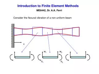
1. MECH3300 Finite Element Methods Lecture 6
Loads and displacement boundary conditions
2. Equal work principle Loads can only be applied at the nodes of a finite element model. Hence equivalent nodal loads need to be found to represent distributed loading.
A finite element model is an expression of a work-energy balance. Just as the stiffness terms are derived from a strain energy expression, so the loads to apply to nodes are derived from the work done by distributed loads.
Principle: Equivalent nodal loads acting on the displacements at the nodes do the same amount of work as the distributed loads acting on the interpolated displacements.
This principle can be applied to each element in turn. It can also be included with finding the stiffness values. We make (potential energy - work done) V - W stationary when each nodal displacement is varied. The equation for node i is
3. Equivalent loads For a 2D element, the work done by a force of f per length over incremental length dl on a displacement u in the same direction is, for linear elastic behaviour dW = 1/2 (f dl) u
The total work over one side of the element is W = 1/2 ?uf dl
But u = N1 u1 + N2 u2 for linear interpolation along the edge.
Hence, dW = 1/2 N1 f dl u1 + 1/2 N2 f dl u2 = 1/2 dF1 u1 +1/2 dF2 u2
Thus nodal loads are F1 = ? N1 f dl and F2 = ? N2 f dl
i.e. the nodal loads are found by weighting the load/length by the interpolation function for the node and integrating along the edge of the element.
4. Linear distributed load on an element edge The functions N1 and N2 are as follows. In terms of a coordinate r ranging from �1 to 1 along the side of the element,
u = � (1 � r) u1 + � (1 + r) u2
i.e, at r = -1 u = u1 and at r = 1 u = u2
or N1 = 1/2 (1 - r) and N2 = 1/2 (1 + r)
Using these interpolation functions, a linear variation of load per length can be written in tems of nodal values as
f = N1 f1 + N2 f2
Using this to evaluate ? Ni f dl over a side length of 2a gives nodal loads F1 = 2/3 f1 a + 1/3 f2 a F2 = 2/3 f2 a + 1/3 f1 a
One example of a linear distributed load is hydrostatic pressure on an axisymmetric model, giving a ring load per depth proportional to depth.
5. Uniform loads on linear elements A uniform load on a row of linear elements does NOT give equal nodal loads.
On one element, equal loads are applied to each node. This applies to each element. So end nodes attached to only one element, have half the loading.
6. Loads per volume Gravity and inertia loading lead to loads f per volume. The nodal load at node i is Fi = ? f Ni dV where Ni is the interpolation function equal to 1 at node i only.
For gravity, the load per volume is f = r g r = density
For inertia loading f = -r a where a = acceleration
eg for a spinning disk f = r r w2 radially.
7. Distributed loading on a quadratic element In terms of a natural coordinate r ranging from -1 to 1 over the side of a quadratic element, the interpolation functions are
for the node at r = 1 N1 = (r + 1)r/2
for the node at r = 0 N2 = 1 - r2
for the node at r = -1 N3 = (r - 1)r/2
Due to a uniform load f per length, the nodal loads on one element of side length 2a are in a 1:4:1 ratio as
F1 = f ? N1 dl = fa/3 F2 = f ? N2 dl = 4fa/3 F3 = f ? N3 dl = fa/3
For a row of 3 quadratic elements, the pattern of nodal loads for a uniform load is thus 1:4:2:4:2:4:1. These loads reflect a similar pattern in the stiffness coefficients.
8. Displacement boundary conditions As mentioned in lecture 3, we can add extra equations to the set to be solved, that describe constraints on the values that nodal displacements can adopt. A general linear constraint equation is of the form A1u1 + A2u2 + A3u3 + �.. = B
Special cases:
u1 = B ie. An imposed displacement
u1 = u2 equating displacements
u1 = (-A2/A1) u2.
This can correspond to fixing a node in a direction other than an axis direction. e.g. regard u1 as an x displacement and u2 as the y displacement at a particular node. To stop motion at angle q from x we want u1 cos q + u2 sin q = 0.
9. Applications of constraint equations Plate elements have rotations at the nodes, solid elements do not. To join the two together, one way is to use a constraint equation to make the rotation of the plate match an appropriate difference in displacements at nodes of the solid element.
A shrink fit is an imposed difference in radial displacements between the shaft and the component fitted on it.
uhub - ushaft = interference on radius (a �shrink link� in STRAND7)
If a material is much stiffer than the rest of the model, it can be made to act rigid by linking its nodes so they move in accord with rigid body motion. (a �rigid link� in STRAND7) eg modelling a rubber component between 2 stiff steel plates.
10. Lagrange multiplier method An effective way to implement constraint equations is to use the Lagrange multiplier method. To illustrate how it works, consider 2 springs. We wish to use a Lagrange multiplier l to make u1 = u2
11. Lagrange multipliers continued The previous energy expression is differentiated wrt u1 , u2 and l in turn, giving
12. Penalty methods An alternative way of enforcing a constraint is to introduce a large stiffness term to penalize violation of the constraint. This is often done to model contact. A stiffness of say 1000 times that found elsewhere is introduced between two nodes in contact, only if inter-penetration is occurring.
This is called a gap element. It can only model small amounts of sliding, but copes with separation of contacting surfaces.