MESF593 Finite Element Methods
MESF593 Finite Element Methods. HW #4 11:00pm, 10 May, 2010. Prob. #1 (10%). T 1. a 1 , CTE 1 , E 1. a 3 , CTE 3 , E 3. a 2 , CTE 2 , E 2. z. z. z. z. T 2. x. y. y. x. (a) Front View. (b) Edge View. T 1. a 1 , CTE 1 , E 1. a 3 , CTE 3 , E 3. a 2 , CTE 2 , E 2. T 2.

MESF593 Finite Element Methods
E N D
Presentation Transcript
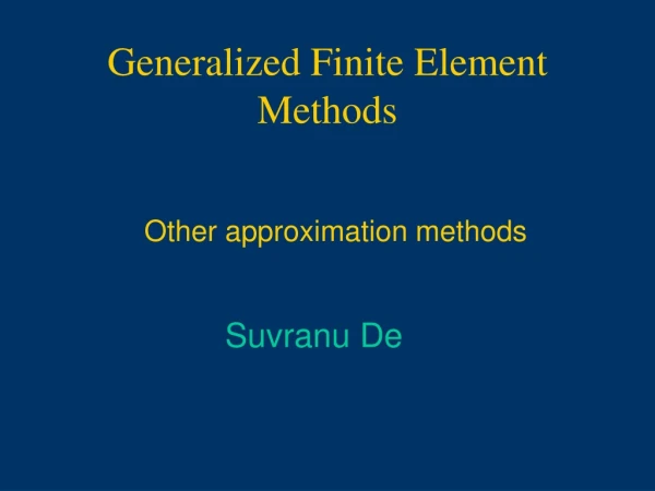
MESF593 Finite Element Methods HW #4 11:00pm, 10 May, 2010
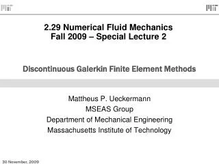
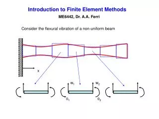
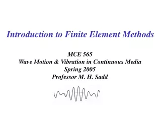
Prob. #1 (10%) T1 a1 , CTE1 , E1 a3 , CTE3 , E3 a2 , CTE2 , E2 z z z z T2 x y y x (a) Front View (b) Edge View T1 a1 , CTE1, E1 a3 , CTE3 , E3 a2 , CTE2 , E2 T2 (c) Front View (d) Edge View A structure consists of 3 different materials and is modeled by 3D brick elements (8-nodes per element) as shown in Figs. (a)/(b). According to the discussion in the class, for heat conduction analysis, the sphere-like joints can be replaced by an equivalent model using bar elements (2-nodes per elements) as shown in Figs. (c)/(d). Such replacement can give quite similar results. However, if you perform thermal-mechanical analysis, you will find the model in Figs. (a)/(b) having stresses due to the mismatch of CTEs while the model in Figs. (c)/(d) with no stress at all. Why? a=k/rC: Thermal Diffusivity CTE: Coefficient of Thermal Expansion E: Young’s Modulus T1: Temp. at the Top Surface of Material 1 T2: Temp. at the Bottom Surface of Material 2 T1 > T2 , CTE1 > CTE2 ,CTE3 = 0
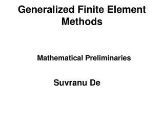
Prob. #2 (20%) F(x) x = 2 x = 18 A quadratic function F(x) is defined as shown above in the range between x = 2 and x = 18. Use the 1-point, 2-point, and 3-point, respectively, Gauss-Legendre quadrature method to evaluate the area underneath the blue curve and compare these numerical integration values to the analytical solution obtained from calculus.
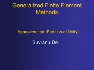
Prob. #3 (35%) I L 1 3 III II L/2 L/2 2 A structure is modeled with 3 linear bar elements (2-nodes per element). All 3 bars have the same Young’s modulus (E), density (r), and area of cross-section (A). The bar lengths are L, L/2 and L/2, respectively, as shown above. The 2 red nodes are rigidly tied together. Also, the 2 orange nodes are rigidly tied together as well. Use the consistent mass formulation to estimate the natural frequencies and the harmonic vibration mode shapes. (Note: the vibration is only allowed in the horizontal direction)
Prob. #4 (35%) I II P III Tg A green circular plate has a triangular hole inside. There is a heat source, denoted by the red dot (with a total power generation of P), at the center of the triangular hole and it is connected to the green plate through 3 bars. The thermal conductivity, area of cross-section, and length of each bar are given as shown above. Assuming there is a uniform temperature Tgover the whole green plate, find the temperature Tr at the red dot and the heat flux through each bar.