Microcomputer Organization
900 likes | 1.32k Views
Microcomputer Organization. Topics to Cover…. Microcomputer structures (Von Neumann vs. Harvard, Refer to 1x/4x User Guide, finding inf ) RISC vs.CISC Computer ISA Anatomy of an Instruction MSP430 ISA Assembler Primer MSP430 Instruction Formats MSP430 Addressing Modes

Microcomputer Organization
E N D
Presentation Transcript
Topics to Cover… • Microcomputer structures (Von Neumann vs. Harvard, Refer to 1x/4x User Guide, finding inf) • RISC vs.CISC • Computer ISA • Anatomy of an Instruction • MSP430 ISA • Assembler Primer • MSP430 Instruction Formats • MSP430 Addressing Modes • MSP430 Instruction Length • MSP430 Instruction Disassembly
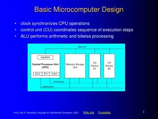
Base Microcomputer Structure Chapter 3 - ISA
Typical Microcontroller Chapter 3 - ISA
According to the MSP430x1xx User Guide… Sometimes the challenge is just where to find info RISC = Reduced Instruction Set Computer What does a RISC microarchitecture look like?
MSP430 Based on RISC architecture- MIPS Chapter 3 - ISA
ISA Instruction Set Architecture • The computer ISA defines all theprogrammer-visible components and operations of the computer (shared vs. non-shared info) • Memory organization • address space -- how may locations can be addressed? • addressibility -- how many bits per location? • Register set • how many? what size? how are they used? • Instruction set • opcodes • data types • addressing modes • ISA provides all information needed for someone that wants to write a program in assembly language(or translate from a high-level language to assembly language).
DATA MEMORY INSTRUCTION MEMORY Control & Address Data Instruction Control ALU CONTROL IN OUT CLOCK Status Von Neumann vs. Harvard Harvard Architecture • The Harvard architecture is a computer architecture with physically separate storage and signal pathways for instructions and data.
Address Bus Data Bus ALU Program Counter Instruction Register Von Neumann vs. Harvard The Von Neumann Computer MEMORY OUTPUT * monitor * printer * LEDs * D/A * disk INPUT * keyboard * mouse * scanner * A/D * serial * disk PROCESSING UNIT Von Neumannproposed this model in 1946 Registers Clock Control Logic The Von Neumann model:Program instructions and Data are both stored as sequencesof bits in computer memory Datapath Control
Von Neumann MSP430 Architecture Processing Unit (CPU) Instructions and Data Input / Output
RISC vs. CISC A Closer look at RISC vs. CISC Architecture RISC CISC Stanford
C Floating Point Multiply -> Assembly Chapter 3 - ISA
RISC vs. CISC RISC / CISC Architecture RISC CISC • Single-clock (Crit Path) • Reduced instructions • No microcode • Data explicitly accessed • Easier to validate • Larger code sizes (~30%) • Low cycles/second • More transistors on memory registers • Pipelining friendly • Emphasis on software (cheap) • Multi-clock • Complex instructions • Complicated microcode • Memory to memory operations • Difficult to validate • Smaller code sizes • High cycles/second • More transistors for complex instructions • Compiler friendly • Emphasis on hardware (expensive)
IA-32 (CISC) MSP430 (RISC) Special Jump Arithmetic Logical RISC vs. CISC RISC/CISC Instruction Set 27 Instructions
RISC vs. CISC Review • What best differentiates RISC and CISC architectures? Compiler friendly Complex instructions Complicated microcode Data explicitly accessed Emphasis on hardware Emphasis on software Fewer instructions High cycles/second RISC RISC CISC CISC Larger code sizes (~30%) Memory to memory operations More CPU transistors Multi-clock instructions No microcode Pipelining friendly Single-clock instructions Smaller code sizes
Computer Instructions Computer Instructions • Computer program consists of a sequence of instructions • instruction = verb + operand(s) • stored in memory as 1’s and 0’s • called machine code. • Instructions are fetched from memory • The program counter (PC) holds the memory address of the next instruction (or operand). • The instruction is stored internal to the CPU in the instruction register (IR). • Programs execute sequentially through memory • Execution order is altered by changing the Program Counter. • A computer clock controls the speed and phases of instruction execution.
Address Bus Data Bus
MSP430 Registers MSP430 Registers
Machine vs Assembly Code Machine Code Assembly Code 0100000000110001 mov.w #0x0600,r1 0000011000000000 0100000010110010 mov.w #0x5a1e,&0x0120 Assembler 0101101000011110 0000000100100000 0100001100001110 mov.w #0,r14 0101001101011110 add.b #1,r14 1111000001111110 and.b #0x0f,r14 0000000000001111 Disassembler 0001001000110000 push #0x000e 0000000000001110 1000001110010001 sub.w #1,0(r1) 0000000000000000 0010001111111101 jne $-4 0100000100111111 mov.w @r1+,r15 Computer Instructions
ele271.com Chapter 3 - ISA
Computer Instructions Anatomy of Machine Instruction “Add the value in Register 4 to the value in Register 5” add r4,r5 0101010000000101 How many source/destination registers can selected with a 4-bit field? 1. Verb –Opcode (0, 1, or 2 operands) 2. 1st object – Source Operand How many instructions are possible with a 4-bit op-code? 3. 2nd object – Destination Operand
Computer Instructions Instruction Addressing Modes • Machine language instructions operate (verb) on operands (objects). • Addressing modes define how the computer identifies the operand (or operands) of each instruction. • Operands are found in • registers, • instructions, or • memory. • Memory operands are accessed • directly, • indirectly (pointer), or • indexed.
MSP430 ISA RISC/CISC machine 27 orthogonal instructions 8 jump instructions 7 single operand instructions 12 double operand instructions 4 basic addressing modes. 8/16-bit instruction addressing formats. Memory architecture 16 16-bit registers 16-bit Arithmetic Logic Unit (ALU). 20-bit address bus (1M address space) 16-bit data bus (8-bit addressability) 8/16-bit peripherals MSP430 ISA
MSP430 ISA MSP430 Bus Architecture • Memory Address Bus (uni-directional) • Address Space = number of possible memory locations (also called the memory size) • Memory Address Register (MAR) stores the memory address for the address bus (address space) • Addresses peripherals as well as memory • Memory Data Bus (bi-directional) • Addressability = number of bits stored in each memory location • Memory Select (MSEL) connects an addressed memory location to the data bus • Memory Write Enable (MWE) is the control signal that is asserted when writing to memory
MSP430 ISA MSP430 Basic Memory 0xFFFF • Memory • 64k byte addressable, address space (0x00000 – 0xFFFF) • Flash / ROM - Used for both code/data • Interrupt vectors - Upper 16 words • RAM - Volatile storage • Peripherals • 0x0100 – 0x01FF 16-bit peripherals • 0x0010 – 0x00FF 8-bit peripherals • Special Function Registers - Lower 16 bytes • Input / Output • Used to get information in and out of the computer. • External devices attached to a computer are called peripherals. • Lower 512 (0x0000 – 0x01FF) of address space Flash (ROM) RAM I/O 0x0000
Basic MSP430 Memory Map 64kB Chapter 3 - ISA
0xFFFF=64kB…where to put the extra 192kB? Chapter 3 - ISA
MSP430F5438 added more Flash - See .map file flash 0x10000 0x5c00 Chapter 3 - ISA
MSP430 ISA MSP430 ALU Architecture • ALU (Arithmetic and Logic Unit) performs the arithmetic and logical operations • Arithmetic operations: add, subtract • Logical operations: and, xor, bit • Sets condition codes • The word length of a computer is the number of bits processed by the ALU. • Sixteen 16-bit registers • Program Counter (R0), Stack Pointer (R1), Status Register (R2) Constant Generator (R3), General Purpose Registers (R4-R15) • Very fast memory - close to the ALU (register file).
MSP430 ISA MSP430 Control Architecture • Clock • System and peripheral clocks • Control Unit • The control unit directs the execution of the program • The program counter or PC points to the next instruction to be executed • The instruction register or IR contains the current executing instruction • The status register or SR contains information about the last instruction executed as well as system parameters • The control unit prevents bus conflicts and timing/propagation problems • The control unit is a Finite State Machine driven by a clock
16 bit Arithmetic Logic Unit (ALU). Performs instruction arithmetic and logical operations. Instruction execution may affect the state of the following status bits: Zero (Z) Carry (C) Overflow (V) Negative (N) The MCLK (Master) clock signal drives the CPU and ALU logic. MSP430 ALU MSP430 ALU
MSP430 ISA Review 1. What is an ISA? 2. List distinctive properties of the MSP430 ISA. It’s a list of programmer-visible instructions and operations. Literally, it’s the set of instructions. This means it tells the programmer the allowed operations or commands that the device can perform. What it’s not: It does not say how the instructions are performed (proprietary vs. open) it only gives the programmer minimum info required: how many registers, alu operations, memory. 16-bit. Small ISA: RISC-like. Von-Neumann. Large number of registers: 16
MSP430 Instructions The first 4-bits (nybble) of an instruction is called the opcode and specifies not only the instruction but also the instruction format. The MSP430 ISA uses three formats to encode instructions for processing by the CPU core: double operand, single operand, and jumps. Single and double operand instructions process word (16-bits) or byte (8-bit) data operations. (Default is word) Complete orthogonal instruction set – Although the MSP430 architecture implements only 27 instructions, every instruction is usable with every addressing mode throughout the entire memory map. High register count, page free, stack processing, memory to memory operations, constant generator. Instruction Formats
MSP430 Instructions 0000 Opcode 0001 0010 0011 0100 0101 0110 0111 4 to 16 Decoder 1000 1001 1010 1011 1100 1101 1110 1111 Instruction Formats Program Counter (R0) Instruction Register
MPS430 Instruction Formats Format I: Instructions with two operands: MSP430 Instructions • Format II: Instruction with one operand: • Format III: Jump instructions:
Format I: Double Operand Double operand instructions: Double Operand Instructions
Example: Double Operand Copy the contents of a register to another register Assembly: mov.w r5,r4 Instruction code: 0x4504 One word instruction The instruction instructs the CPU to copy the number in register r5 to register r4 Double Operand Instructions
Format II: Single Operand Single operand instructions: Single Operand Instructions
Example: Single Operand Logically shift the contents of register r5 to the right through the status register carry Assembly: rrc.w r5 Instruction code: 0x1005 One word instruction The CPU shifts the 16-bit register r5 one bit to the right (divide by 2) – the carry bit prior to the instruction becomes the MSB of the result while the LSB shifted out replaces the carry bit in the status register Single Operand Instructions