Download
1 / 34
340 likes | 457 Views
Unified Modeling Language (UML) is a standardized visual language used to specify, visualize, and construct software artifacts. It is not only confined to software but is also applicable in business modeling. This overview will explore UML's history, goals, diagram types, and latest developments. UML facilitates meaningful model sharing among developers, enables comparisons before implementation, and stimulates the growth of object-oriented tools. Learn about its various diagram types, including class and state diagrams, and understand its role in modeling large and complex systems.

E N D
Unified Modeling Language(UML)BY Touseef Tahir Touseeftahir@ciitlahore.edu.pk Lecturer CS COMSATS Institute of Information Technology, Lahore
Overview • Introduction • History • Goals • Diagrams and Examples • Latest Changes • Disadvantages • Conclusion
What is UML? • Unified Modeling Language (UML) is a standard language for specifying, visualizing, constructing software artifacts. • Not necessarily restricted to software systems – used in business modeling. • Has proven successful in modeling of large and complex systems. • Uses graphical notations to describe the architecture of software.
Goals • Provide users a expressive, visual language to enable sharing of meaningful models. • Enables developers to compare models before implementation phase. • Independent of programming language and development process. • Encourage growth of Object Oriented Tools market.
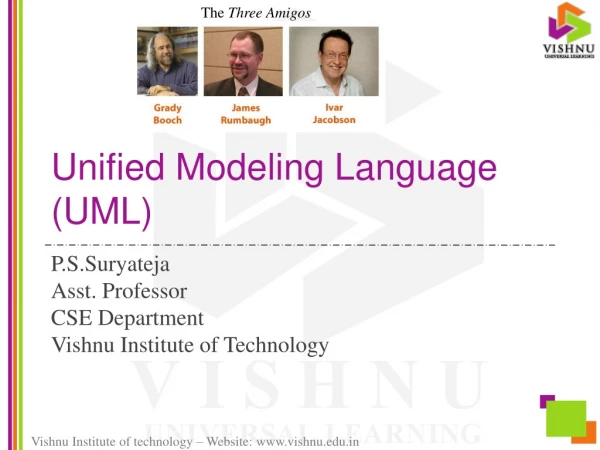
History • First modeling languages – 1970’s. • More than 50 modeling languages present during 1994. Lead to “method wars”. • Methods began to incorporate each other’s techniques. • In 1994, Grady Booch and Jim Rumbaugh (Rational Software Corporation) unified Booch and Object Modeling Technique methods to create UML. • Ivar Jacobson incorporated the OOSE method in 1995, leading to UML version 0.9 in late 1996.
UML Versions • UML 1.0 was created through a collaboration of various organizations: Microsoft, IBM, HP, etc. • Today, UML is on Version 2.0. • It is managed by the Object Management Group – not for profit consortium. UML specification is available for download at http://www.uml.org/ • Tools that conform the latest 2.0 specification – Rational Software Architect, Sparx System Architect, Star UML, etc.
Class diagram • Abstraction • Inheritance • Polymorphism • Encapsulation • Message Sending • Associations • Multiplicity • Aggregation
Inheritance • Generalization in UML
Aggregation • Two types of Association • Part-whole association • Composition
Aggregation • Part-whole association • Multiplicity
Aggregation • Multiplicity
Aggregation • Composition • A strong type of aggregation. Each component in composite can belong to just one whole. • The Diamond shape used for composition is same but its just filled.
Package • UML Packages are a grouping of objects into sets of objects that provide related services. The package has responsibilities that are strongly related. • Coupling & cohesion
State Diagrams • State diagram • Behavior of systems • Finite number of states • Components of state diagram
State diagram • An object’s state and behaviour can be affected by: • Changes to attribute values • Results of operations • Changes of links with other objects • Internal events • External events
Three models • Object model: • Static structure of objects in a system and their relationships. • Contains class diagrams. • dynamic model; • describes aspects that change over time: state transition diagrams • functional model; • Use Case diagrams
State and Events • A state is an abstraction of the attribute. Sets of values are grouped together into a state according to properties that affect the gross behaviour of the object. • A change of state is called a transition
Event classes • Event occurrences are grouped into event classes • Flight 123 departs from Chicago / Flight 456 departs from Rome • Event class is Flight Departs • Attributes of event classes • Departure origin of flight • Flight number • destination • Data values are Attributes
Event Classes and Attributes • Aeroplane flight departs (airline, flight no, city) • Mouse button pushed (button, location) • Input string entered (text) • phone receiver lifted( True, False) • digit dialled (digit) • engine speed enters danger zone
Events • Something that happens at a point in time • Mouse button clicked / Signal changes • Logically ordered events - causally related • Concurrent events - causally unrelated • do not effect each other • there is no order between them • 1-way transmission of information from one object to another
Characterisations of a state • State: Alarm ringing • Description: alarm on watch is ringing to indicate target time • Event sequence that produces the state: • set alarm (target time) • any sequence not including clear alarm • current time = target time
How to make state diagram • Identify states and identify which variables identify states • Identify events • Create state chart • Create state table with all finite stated and event